A foreign body removal device for otolaryngology
A technology for removing devices and foreign bodies, applied in medical science, ear treatment, surgery, etc., can solve the problems of poor comfort and low efficiency of removing small foreign bodies, and achieve the effects of improving efficiency, saving manpower and improving comfort.
- Summary
- Abstract
- Description
- Claims
- Application Information
AI Technical Summary
Problems solved by technology
Method used
Image


Examples
Embodiment 1
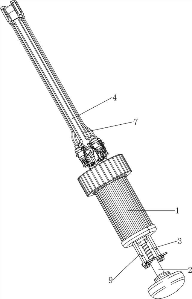
[0069] An otolaryngology foreign body removal device, such as Figure 1-Figure 3 As shown, it includes a hand-held block 1, a first push block 2, a first spring 3, an air suction pipe 4, a balloon 5, a second spring 6, a spreading mechanism 7 and a clamping mechanism 8. The lower part of the hand-held block 1 is slidably arranged. There is a first push block 2, a first spring 3 is sleeved on the first push block 2, the two ends of the first spring 3 are respectively connected to the hand-held block 1 and the first push block 2, and the upper part of the hand-held block 1 is slidably provided with an air suction Pipe 4, a balloon 5 is provided inside the hand-held block 1, the balloon 5 is matched with the first push block 2, the upper part of the balloon 5 is connected with the lower part of the air suction pipe 4, and the lower part of the air suction pipe 4 is sheathed with a second spring 6, and the second spring 6 is two. The ends are respectively connected to the hand-hel...
Embodiment 2
[0072] In a preferred embodiment of the present invention, as Figure 4 and Figure 5 As shown, the opening mechanism 7 includes a connecting block 71, a first swinging block 72, a supporting block 73, a first bracket 74, a second swinging block 75, a rotating shaft 76 and a torsion spring 77, and the lower part of the air suction pipe 4 is evenly provided with connecting blocks Block 71, the number of connecting blocks 71 is four, the first swing block 72 is rotatably provided on the four connecting blocks 71, the upper part of the hand-held block 1 is provided with a support block 73, and the support block 73 is slidably matched with the air suction pipe 4, The upper four sides of the support block 73 are evenly provided with first brackets 74 . The number of the first brackets 74 is eight. A rotating shaft 76 is rotatably provided between the two first brackets 74 located on the same side. There is a second swing block 75 , the lower part of the second swing block 75 is ro...
Embodiment 3
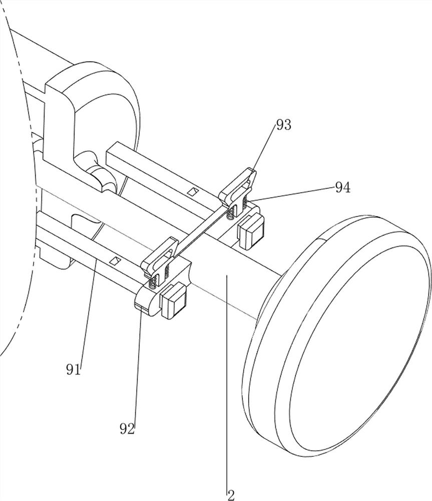
[0077] In a preferred embodiment of the present invention, as Figure 6-Figure 9 As shown, it also includes a limiting mechanism 9, the limiting mechanism 9 includes a second sliding rod 91, a slider 92, a clamping block 93 and a fourth spring 94, and two second sliding rods 91 are arranged at the bottom of the hand-held block 1 at intervals, There are sliding blocks 92 on the front and rear sides of the middle of the first push block 2. The sliding blocks 92 are slidably connected with the second sliding rods 91 located on the same side. A clamping block 93 is slidably provided between the two sliding blocks 92. The clamping block 93 is matched with the second sliding rod 91 , a fourth spring 94 is connected between the clamping block 93 and the sliding block 92 , and the number of the fourth springs 94 is four.
[0078] It is inconvenient for people to press the first push block 2 to adjust the air suction pipe 4. Therefore, when the first push block 2 slides upward, the fir...
PUM
 Abstract
Description
Claims
Application Information
 - R&D
- Intellectual Property
- Life Sciences
- Materials
- Tech Scout
- Unparalleled Data Quality
- Higher Quality Content
- 60% Fewer Hallucinations
Browse by: Latest US Patents, China's latest patents, Technical Efficacy Thesaurus, Application Domain, Technology Topic, Popular Technical Reports.
© 2025 PatSnap. All rights reserved.Legal|Privacy policy|Modern Slavery Act Transparency Statement|Sitemap|About US| Contact US: help@patsnap.com