Rotary kiln with material turning function

A technology of rotary kiln and material turning, applied in the field of rotary kiln, can solve the problems such as the inability to turn the material inside the hazardous waste stack to the outside, the hazardous waste cannot be heated evenly, and the degree of tumbling is limited.

Pending Publication Date: 2021-10-01
高邮市环创资源再生科技有限公司 +1
View PDF0 Cites 3 Cited by
  • Summary
  • Abstract
  • Description
  • Claims
  • Application Information

AI Technical Summary

Problems solved by technology

[0003] The technical problem to be solved by the present invention is: in order to solve the problem that the degree of tumbling of hazardous waste in the rotary kiln is limited due to the action of gravity, so that the internal materials of the hazardous waste stack cannot be turned over to the outside, and the hazardous waste cannot be heated evenly Problem, the present invention provides a rotary kiln with a material turning function, adding a material turning mechanism, the linkage piece can drive the telescopic baffle protruding from the telescopic frame to move synchronously after the linkage rotates with the drum, and the telescopic baffle drives the rotating ring sleeve Rotate on the installation shaft. During this process, the telescopic baffle and the telescopic frame cooperate to scoop up part of the hazardous waste in the drum. This part of hazardous waste reaches a high place and then scatter naturally. After reaching a high place, the telescopic baffle can automatically It retracts into the telescopic frame, and when the telescopic frame rotates to a low position, it can extend out by its own gravity. In this cycle, the linkage can indirectly push the rotating ring to rotate when it rotates with the drum, so that the hazardous waste can continue to turn over. material

Method used


Image

  • Rotary kiln with material turning function
  • Rotary kiln with material turning function
  • Rotary kiln with material turning function

Examples


Embodiment Construction

[0031] The technical solutions of the present invention will be clearly and completely described below in conjunction with the accompanying drawings. Apparently, the described embodiments are some of the embodiments of the present invention, but not all of them.

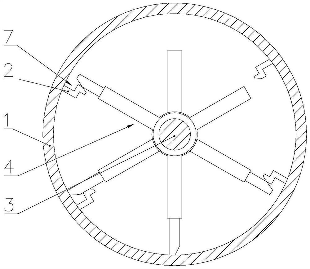
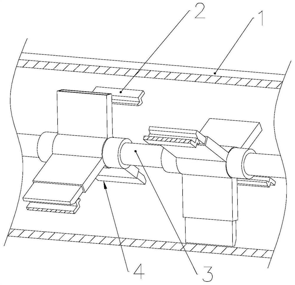
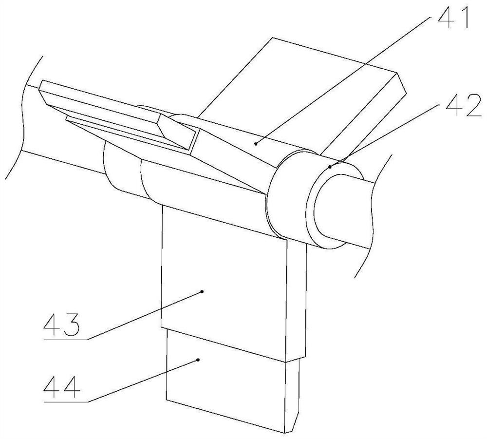
[0032] Such as Figure 1-10As shown, a rotary kiln with a material turning function includes: a kiln head, a drum 1 and a kiln tail. The drum 1 is obliquely arranged on the kiln head and the kiln tail. There is a linkage 2 on it, and the linkage 2 is used to drive the material turning mechanism 4 to carry out the material turning operation. The material turning mechanism 4 includes a rotating ring sleeve 41 and two limit slides 42, and the rotating ring sleeve 41 is provided with three equiangular angles. The provided telescopic frame body 43 is provided with a telescopic baffle plate 44 that slides and fits therein. After the telescopic baffle plate 44 stretches out, it can abut and cooperate with the linkage 2. The...


PUM


Abstract

The invention belongs to the technical field of mechanical equipment, and relates to a rotary kiln with a material turning function. The rotary kiln comprises a kiln head, a roller and a kiln tail, wherein the roller is obliquely arranged on the kiln head and the kiln tail, the rotary kiln further comprises a mounting shaft and a material turning mechanism, a linkage part is arranged on the inner wall of the roller and is used for driving the material turning mechanism to perform material turning operation, the material turning mechanism comprises a rotating ring sleeve and two limiting sliding seats, three telescopic frames are arranged on the rotating ring sleeve, telescopic baffles are arranged in the telescopic frames, a secondary propelling assembly is arranged in a mounting groove, a sealing cover is arranged at the inner side end of each telescopic baffle, the telescopic frames communicate with the rotating ring sleeve, the two limiting sliding seats are arranged on the mounting shaft at intervals, a pop-up assembly is arranged on the right lower side wall of the mounting shaft, the mounting shaft is mounted on the kiln head and the kiln tail, the mounting shaft and the roller are coaxial, and the material turning mechanism is rotationally arranged on the mounting shaft. According to the rotary kiln, the dangerous waste can be continuously turned over, so that the dangerous waste is uniformly heated in the roller.

Description

technical field [0001] The invention relates to the technical field of mechanical equipment, in particular to a rotary kiln with a material turning function. Background technique [0002] The rotary kiln for hazardous waste treatment originated from the main thermal equipment of alumina plants, cement plants and other metallurgical and chemical plants. Since the device was introduced into China, it has gradually become the main equipment for the harmless disposal of hazardous waste, and has been widely used in the industry. During processing, hazardous waste can be continuously rolled in the drum of the rotary kiln to achieve the purpose of homogenizing the heating of hazardous waste. However, the degree of tumbling of hazardous waste in the rotary kiln is limited due to the action of gravity, so that the internal materials of the hazardous waste stack are often unable to be turned outside, and the hazardous waste cannot be heated evenly. Contents of the invention [000...

Claims


Application Information

Patent Timeline
Patent Type & Authority Applications(China)
IPC IPC(8): F27B7/20F27B7/22F27D3/00
CPCF27B7/20F27B7/22F27D3/00F27D2003/0034F27D2003/0083F27B7/18
Inventor 周品赵瑜黎洁朱长进杨海明
Owner 高邮市环创资源再生科技有限公司
Why Eureka
Try Eureka