Hardware perforating device

A punching device and hardware technology, applied in positioning devices, metal processing equipment, metal processing machinery parts, etc., can solve the problems of low punching efficiency, complicated fixing process, hardware punching error, etc., and achieve faster punching speed. , The punching position is accurate, the effect of good buffering effect

Inactive Publication Date: 2019-01-04
邢建
View PDF0 Cites 0 Cited by
  • Summary
  • Abstract
  • Description
  • Claims
  • Application Information

AI Technical Summary

Problems solved by technology

[0005] In order to make up for the deficiencies of the existing technology, the incomplete fixation of the hardware will lead to errors in the drilling of the hardware, and in severe cases, the hardware will be damaged and scrapped, the fixing process is too complicated, and the temperature during the drilling of the hardware is too high, resulting in the service life of the drill pipe. low and low punching efficiency, a kind of hardware punching device proposed by the present invention

Method used


Image

  • Hardware perforating device
  • Hardware perforating device
  • Hardware perforating device

Examples


Embodiment approach

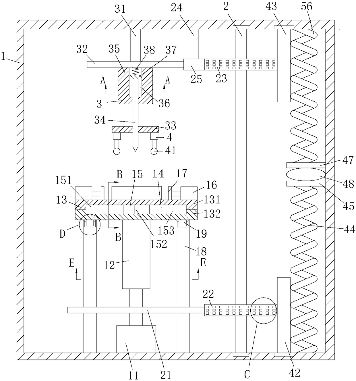
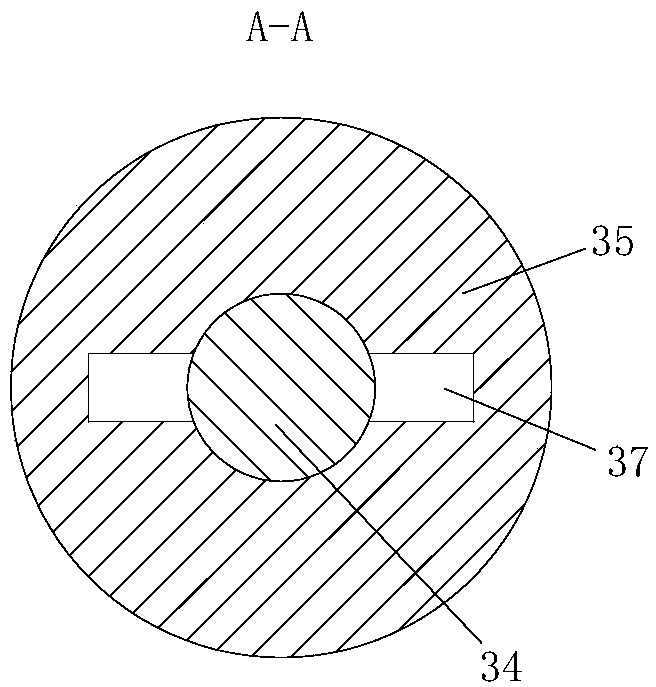
[0026] As an embodiment of the present invention, the punching unit 3 includes a third fixed rod 31, a fifth gear 32, a fixed plate 33 and a drill rod 34; one end of the third fixed rod 31 is fixedly connected to the top of the frame body 1. On the inner wall, the other end is rotatably connected with a fifth gear 32; the fifth gear 32 meshes with the fourth gear 25; the lower surface of the fifth gear 32 is fixedly connected with a rotating block 35; the rotating block 35 defines a limit Groove 36; a drill rod 34 is provided under the rotating block 35; the upper surface of the drill rod 34 is fixedly connected with a limiting block 37; the limiting block 37 fits with the limiting groove 36, and the upper end of the drill rod 34 penetrates In the limiting groove 36, a first spring 38 is fixedly connected to the inner wall of the top of the limiting groove 36; a fixing plate 33 is arranged under the fifth gear 32; the fixing plate 33 is fixed to the inner wall of the frame 1; T...


PUM


Abstract

The invention belongs to the technical field of hardware machining and particularly relates to a hardware perforating device. The hardware perforating device comprises a frame body. A torsion bar is fixedly connected to an upper end of a rotary shaft of a motor. The torsion bar is made of a rubber material. A supporting plate is fixedly connected to an upper end of the torsion bar. The supportingplate is divided into two portions of an upper plate and a lower plate. First air cylinders are fixedly connected to two ends of an upper surface of the supporting plate. Stretching ends of the firstair cylinders are fixedly connected with fixing blocks correspondingly. A limiting groove is formed in a rotary block. A drilling rod is arranged below the rotary block. A limiting block is fixedly connected with an upper surface of the drilling rod. Thread grooves are formed in a rotary manner inside an opening. Threads are arranged in a rotary manner in the surface of the drilling rod. The threads are engaged with the thread grooves. Second air cylinders are arranged on both the left side and the right side of the drilling rod. The upper surface of the upper plate of the supporting plate isobliquely arranged, and uniformly arranged third airbags are arranged on the upper surface of the upper plate. Tops of the third airbags are located in the same horizontal line. According to the hardware perforating device, perforating efficiency is high; perforating error rate is low; the service life is long; the structure is simple; and the device is convenient to use.

Description

Technical field [0001] The invention belongs to the technical field of hardware processing, and specifically is a hardware punching device. Background technique [0002] Traditional hardware parts are also called small hardware and hardware accessories. Refers to various metal appliance parts made by forging, rolling, cutting and other physical processing of iron, steel, aluminum and other metals. It can be used alone or as an auxiliary appliance. The hardware parts include mold hardware parts, mechanical hardware parts, Daily hardware parts, window hardware parts, ship hardware parts, construction hardware parts, aerospace hardware parts and security products, etc. The hardware parts are divided into plate parts, pipe parts, etc. according to the different shapes. These parts are in order to The need for subsequent processing usually requires punching. [0003] Some technical solutions for hardware punching devices have also appeared in the prior art. For example, a Chinese pate...

Claims


Application Information

Patent Timeline
Patent Type & Authority Applications(China)
IPC IPC(8): B23Q1/44B23Q1/50B23Q3/08B23Q11/00B23Q11/10
CPCB23Q1/44B23Q1/50B23Q3/08B23Q11/00B23Q11/10
Inventor 邢建王军陈二东
Owner 邢建
Why Eureka
Try Eureka