Eureka AIR delivers breakthrough ideas for toughest innovation challenges, trusted by R&D personnel around the world.

Networking radar resource allocation method based on mutual information maximization

A technology for networking radar and resource allocation, applied in the field of radar, it can solve problems such as high computational complexity, difficulty in obtaining optimal solutions, and difficulty in adapting to real-time requirements, so as to overcome the large amount of computation and solve heterogeneous networking radars. System resource allocation problem and the effect of meeting real-time requirements

Pending Publication Date: 2021-10-01
XIDIAN UNIV
View PDF0 Cites 2 Cited by
  • Summary
  • Abstract
  • Description
  • Claims
  • Application Information

AI Technical Summary

Problems solved by technology

[0004] However, the above method can only be applied to a homogeneous networked radar system, and during resource allocation, different types of resource variables are generally coupled in the tracking information measurement function, and in related technologies, the measured value of each target is calculated sequentially according to the arrival time of each target measurement value tracking information measurement function, the resulting resource allocation problem is non-convex, and it is difficult to obtain an optimal solution; in addition, the Bayesian Cramerot lower bound is used as the tracking information measurement function in related technologies, and its computational complexity is often high, which is difficult to adapt to real-time requirements

Method used


Image

  • Networking radar resource allocation method based on mutual information maximization
  • Networking radar resource allocation method based on mutual information maximization
  • Networking radar resource allocation method based on mutual information maximization

Examples


Embodiment Construction

[0026] The present invention will be described in further detail below in conjunction with specific examples, but the embodiments of the present invention are not limited thereto.

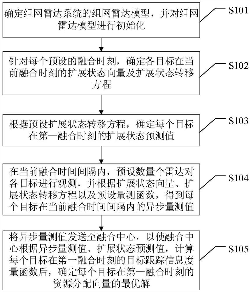
[0027] like figure 1 As shown, the method for allocating networked radar resources based on mutual information maximization provided by the embodiment of the present invention is applied to a networked radar system. The networked radar system includes a fusion center and a preset number of radars. The detection area of ​​the radar includes at least a goal;

[0028] The above-mentioned networked radar resource allocation method based on mutual information maximization includes:

[0029] S101. Determine the networked radar model of the networked radar system, and initialize the networked radar model;

[0030] S102. For each preset fusion moment, determine the extended state vector and the extended state transition equation of each target at the current fusion moment;

[0031] S103. Determine the p...


PUM


Abstract

The invention discloses a networking radar resource allocation method based on mutual information maximization, and relates to the technical field of radars. The method comprises the steps of determining a networking radar model of a networking radar system, and carrying out the initialization of the networking radar model; determining an extended state vector and an extended state transition equation of each target at the current fusion moment; determining an extended state prediction value of each target at the first fusion moment; in the current fusion time interval, observing each target by a preset number of radars, and obtaining an asynchronous measurement value of each target in the current fusion time interval; and sending the asynchronous measurement value to a fusion center so as to enable the fusion center to determine an optimal solution of a resource allocation vector of each target at the first fusion moment after calculating a target tracking information measurement function of each target at the first fusion moment. According to the method, the defect that the objective function is relatively large in computation burden is overcome, and the real-time requirement is met while the resource allocation problem of the heterogeneous networking radar system is solved.

Description

technical field [0001] The invention belongs to the technical field of radar, and in particular relates to a method for allocating networked radar resources based on mutual information maximization. Background technique [0002] Networked radar systems are usually composed of different types of radars. Unlike single-station radars that can only obtain limited target information, networked radar systems can obtain information on different targets from different angles, and have higher tracking accuracy and anti-jamming ability. [0003] However, when the networked radar system is actually applied, its detection resources are very limited, and the resources required to track all targets may exceed the available resources of each radar, which means that the resource constraints of each node and radar station must be considered. Related technologies provide some methods for dealing with the resource allocation problem of multi-target tracking in a networked radar system, so as ...

Claims


Application Information

Patent Timeline
Patent Type & Authority Applications(China)
IPC IPC(8): G01S7/42G06F30/20
CPCG01S7/42G06F30/20
Inventor 严俊坤张聪睿李春霄戴金辉纠博刘宏伟
Owner XIDIAN UNIV
Why Eureka
Eureka Blog
Learn More