
An easy-to-use multi-band combined antenna device

A combined antenna and multi-band technology, applied to antennas, devices that enable antennas to work in different bands at the same time, antenna support/installation devices, etc., can solve problems such as poor wind resistance, signal loss, and inconvenient installation, and achieve guaranteed Normal use, prevent signal loss, and suitable for promotion

Active Publication Date: 2022-04-12
ZHONGTIANXUN COMM TECH
View PDF0 Cites 0 Cited by
  • Summary
  • Abstract
  • Description
  • Claims
  • Application Information

AI Technical Summary

Problems solved by technology

[0004] An easy-to-use multi-band combined antenna device proposed by the present invention solves the problems that the existing antenna device is inconvenient to install with a fixed pole during use and has poor wind resistance performance, which easily leads to signal loss

Method used


Image

  • An easy-to-use multi-band combined antenna device
  • An easy-to-use multi-band combined antenna device
  • An easy-to-use multi-band combined antenna device

Examples


Embodiment 1

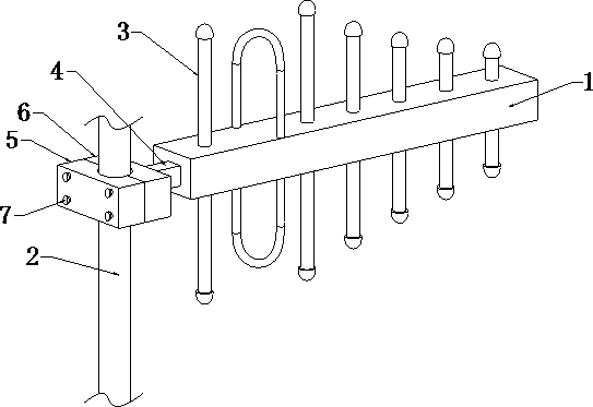
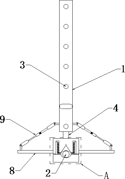
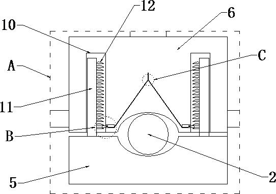
[0029] refer to Figure 1-6 , an easy-to-use multi-band combined antenna device, including a skeleton rod 1, a fixed rod 2, an antenna rod 3 and a positioning device, the skeleton rod 1 is evenly installed with the antenna rod 3, and one end of the skeleton rod 1 is fixedly connected with a connecting end The head 4, the connection end 4 is rotationally connected with the positioning device, and the positioning device is fixedly installed on the outer wall of the fixed rod 2;

[0030] The positioning device includes a first positioning plate 5 and a second positioning plate 6, and the first positioning plate 5 and the second positioning plate 6 are arranged correspondingly on the outer wall of the fixed rod 2;

[0031] Side plates 8 are fixedly connected to both sides of the second positioning plate 6 , and a wind protection device 9 is connected between the two side plates 8 and the side walls of the frame rod 1 respectively.

[0032] The first positioning plate 5 and the se...

Embodiment 2

[0041] refer to figure 2 and Figure 7 , an easy-to-use multi-band combined antenna device, including a skeleton rod 1, a fixed rod 2, an antenna rod 3 and a positioning device, the skeleton rod 1 is evenly installed with the antenna rod 3, and one end of the skeleton rod 1 is fixedly connected with a connecting end The head 4, the connection end 4 is rotationally connected with the positioning device, and the positioning device is fixedly installed on the outer wall of the fixed rod 2;

[0042] The positioning device includes a first positioning plate 5 and a second positioning plate 6, and the first positioning plate 5 and the second positioning plate 6 are arranged correspondingly on the outer wall of the fixed rod 2;

[0043] Side plates 8 are fixedly connected to both sides of the second positioning plate 6 , and a wind protection device 9 is connected between the two side plates 8 and the side walls of the frame rod 1 respectively.

[0044] One side of the first posit...


PUM


Abstract

The invention discloses an easy-to-use multi-band combined antenna device, which relates to the field of antenna devices and aims at the problems that the existing antenna device is inconvenient to be installed with a fixed pole during use and has poor wind resistance performance, which easily leads to signal loss. The following scheme is now proposed, which includes a skeleton rod, a fixed rod, an antenna rod and a positioning device, the antenna rod is uniformly installed on the skeleton rod, and one end of the skeleton rod is fixedly connected with a connecting terminal, and the connecting terminal is connected to the The positioning device is rotatably connected, and the positioning device is fixedly installed on the outer wall of the fixed rod. The structure of the invention is novel, and the device can not only conveniently and quickly install the antenna equipment on different positions of the fixed rods with different sizes, but also enable the antenna equipment to have a certain self-wind protection function, effectively preventing the The signal loss caused by the position deviation ensures the normal use of the antenna equipment and is suitable for promotion.

Description

technical field [0001] The invention relates to the field of antenna equipment, in particular to an easy-to-use multi-band combined antenna equipment. Background technique [0002] An antenna is a transformer that transforms a guided wave propagating on a transmission line into an electromagnetic wave propagating in an unbounded medium, or vice versa. A component used in radio equipment to transmit or receive electromagnetic waves. Engineering systems such as radio communication, broadcasting, television, radar, navigation, electronic countermeasures, remote sensing, and radio astronomy, which use electromagnetic waves to transmit information, rely on antennas to work. In addition, in terms of transmitting energy with electromagnetic waves, non-signal energy radiation also requires antennas. Generally, antennas are reversible, that is, the same antenna can be used as both a transmitting antenna and a receiving antenna. The basic characteristic parameters of the same anten...

Claims


Application Information

Patent Timeline
Patent Type & Authority Patents(China)
IPC IPC(8): H01Q5/28H01Q1/12
CPCH01Q5/28H01Q1/12
Inventor 周凯淦韩振宇苏永红韦进邹毅钱支民龙秋霖熊皓
Owner ZHONGTIANXUN COMM TECH
Learn More