
Spacecraft device and installation method of bend-inserted printed board connector

A space vehicle and connector technology, applied in the field of aircraft, can solve problems such as over-positioning inside the space vehicle device

Active Publication Date: 2020-02-28
BEIJING INST OF RADIO METROLOGY & MEASUREMENT
View PDF11 Cites 0 Cited by
  • Summary
  • Abstract
  • Description
  • Claims
  • Application Information

AI Technical Summary

Problems solved by technology

[0004] This application proposes a space vehicle device and an installation method for an angled printed board connector, aiming at solving the problem of the installation of the angled printed board connector on the front panel of the prior art, and the issue between the angled printed board connector and the circuit board. Over-positioning problems during welding and installation inside spacecraft devices

Method used


Image

  • Spacecraft device and installation method of bend-inserted printed board connector
  • Spacecraft device and installation method of bend-inserted printed board connector
  • Spacecraft device and installation method of bend-inserted printed board connector

Examples


Embodiment 1

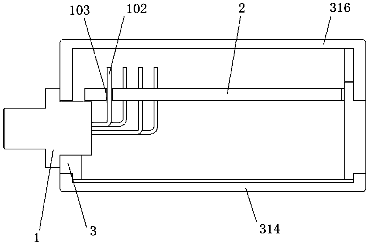
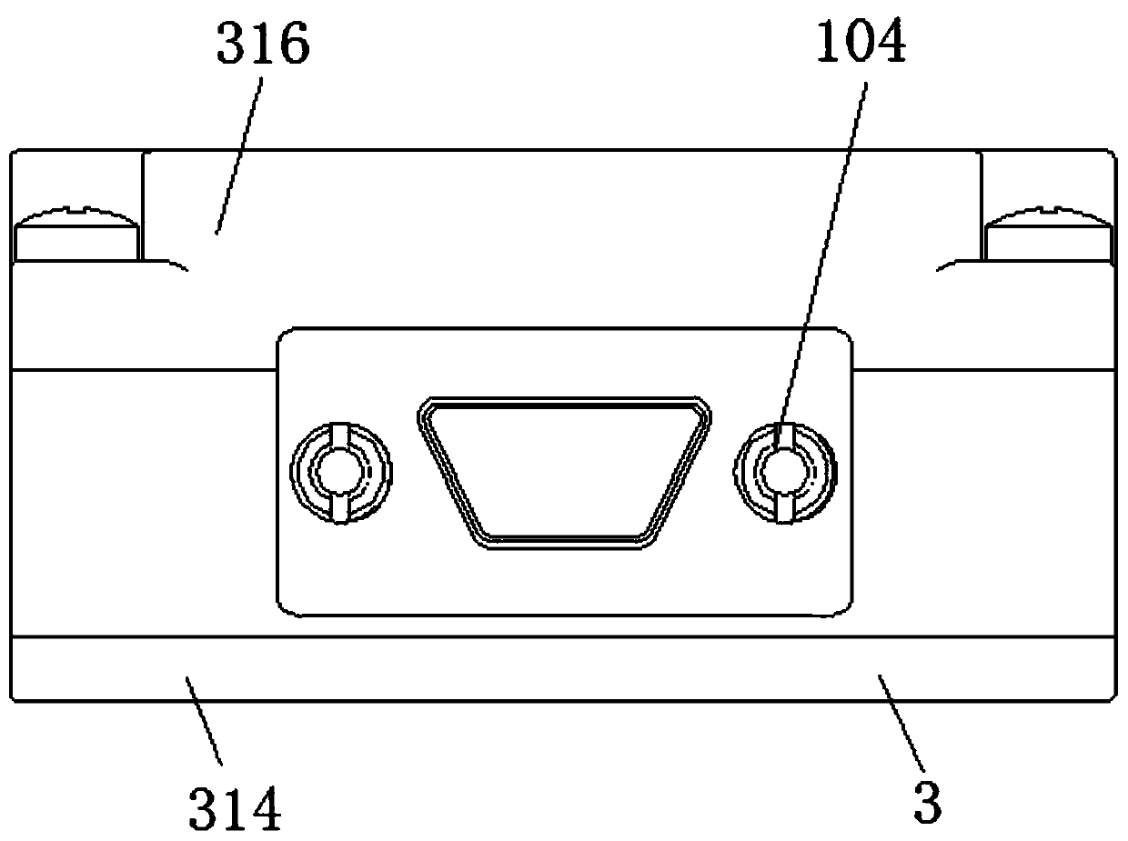
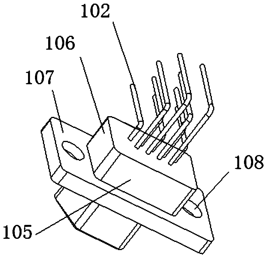
[0089] A space vehicle device, see Figure 1 to Figure 7 , the spacecraft device includes a curved plug printed board connector 1, a circuit board 2 and a structural shell 3;

[0090] The rear end of the bent printed board connector 1 is connected with a connector flange 101, and the bent printed board connector 1 is fixedly installed on the structural shell 3 through the connector flange 101; the bent printed board connector 1 A looper 102 is arranged on the top;

[0091] The circuit board 2 is fixedly installed on the structural shell 3; the circuit board 2 is provided with a connector printed board opening 103 for connecting with the bent-in printed board connector 1, and the connector printed board opening 103 is provided with Welding pad, hook 102 is inserted into the opening 103 of the connector printed board;

[0092] The curved pin 102 bent into the printed board connector 1 is welded to the pad on the opening 103 of the printed board of the connector.

[0093] In t...

Embodiment 2

[0099] A space vehicle device, similar to Embodiment 1, the difference is, see Figure 8 to Figure 23 , the structural shell 3 includes an upper shell 304 and a lower shell 305 combined with each other, and a supporting shell 306; the bent-insert printed board connector 1 includes AX bent-inserted printed board connectors 109 and B with the A face below The BX angled-plug printed board connector 110 on the lower side, the AS angled-in printed board connector 111 on the upper side of the A side, and the BS angled-in printed board connector 112 on the upper side of the B side; the circuit board 2 includes the lower circuit Board 201 and upper circuit board 202; locking member 104 includes upper locking member and lower locking member; groove 301 includes AX groove 307, BX groove 308, AS groove 310 and BS groove 310;

[0100] The AX groove 307 and the BX groove 308 are arranged on the lower housing 305, the AX curved plug printed board connector 109 is arranged in the AX groove 3...

Embodiment 3

[0114] An installation method of a bent-insert printed board connector, the bent-inserted printed board connector 1 is the bent-inserted printed board connector 1 of a space vehicle as described in embodiment 1 or embodiment 2, and the bent-inserted printed board connector 1 Board connector 1 is installed on the space vehicle described in embodiment 1 or embodiment 2, comprises the following steps,

[0115] Fixing the curved plug-in printed board connector 1 on the structural shell 3 through the connector flange 101;

[0116] Fixing the circuit board 2 on the structural housing 3;

[0117] Insert the looper 102 into the opening 103 of the connector printed board;

[0118] Weld the bent pin 102 bent into the printed board connector 1 with the pad on the opening 103 of the printed board of the connector.

[0119] The installation method of the bent-insert printed board connector of this embodiment may specifically connect and fix the bent-inserted printed board connector 1 wit...


PUM


Abstract

The invention discloses a spacecraft device and an installation method of a bend-inserted printed board connector. The spacecraft device comprises a bend-inserted printed board connector, a circuit board and a structural housing. The bend-inserted printed board connector is positioned on the structural housing, the rear end of the bend-inserted printed board connector is connected with a connectorflange, and the bend-inserted printed board connector is provided with a curved needle; the circuit board is positioned and fixed on the structural housing, the circuit board is provided with a connector printed board opening for connecting with the bend-inserted printed board connector, and the curved needle is inserted into the connector printed board opening; the curved needle of the bend-inserted printed board connector is welded with a pad on the printed board opening to form an integrated structure of the bend-inserted printed board connector, the circuit board and the structural housing, realizing cabling-free connection between the bend-inserted printed board connector and the circuit board, improving the utilization rate of the internal space of the spacecraft device, avoiding generation of stress, preventing over-positioning and ensuring product quality. The difficulty of installation, later testing and maintenance is reduced, the performance is more stable, resource consumption is reduced, and the overall performance is improved.

Description

technical field [0001] The present application relates to the technical field of aircraft, and in particular to a space vehicle device and a method for installing a curved plug-in printed board connector. Background technique [0002] At present, the installation methods of connectors and circuit boards of space vehicle devices are mainly divided into two methods: wire connection and printed board welding; among them, wire connection makes a large part of the space for wiring, wasting structural space, and a large number of The cables only play the role of conduction, adding useless quality, and the numerous wire harnesses make it more difficult for skilled workers to operate. The direction and layout of the wires need to be planned by experienced skilled workers, which makes it difficult for personnel to operate and lowers production efficiency. low, and the product quality status is unstable; while the soldering of the printed board removes the wires used for the connectio...

Claims


Application Information

Patent Timeline
IPC IPC(8): H01R12/72H01R13/74H05K5/00B64G1/22
CPCB64G1/22H01R12/724H01R13/748H05K5/0008H05K5/0069
Inventor 赵鹏辉刘庆山周海洋孙雨周洁何鑫谢钊姚铁峰
Owner BEIJING INST OF RADIO METROLOGY & MEASUREMENT
Learn More