
Constructional column steel bar automatic binding device for house building engineering

A technology for construction engineering and structural columns, which is applied in the field of automatic bundling devices for structural column steel bars for housing construction projects, can solve problems such as heavy workload, difficult operation, cumbersome and other problems, reduce the problem of low efficiency, facilitate installation and disassembly, and increase work. The effect of efficiency

Inactive Publication Date: 2021-10-08
张学红
View PDF0 Cites 0 Cited by
  • Summary
  • Abstract
  • Description
  • Claims
  • Application Information

AI Technical Summary

Problems solved by technology

The bundling process is difficult and cumbersome to operate, resulting in low manufacturing efficiency of the reinforcement cage
[0003] At present, manual binding is generally the main method. The problems of manual binding are heavy workload, low efficiency, and certain damage to the human body.

Method used


Image

  • Constructional column steel bar automatic binding device for house building engineering
  • Constructional column steel bar automatic binding device for house building engineering
  • Constructional column steel bar automatic binding device for house building engineering

Examples


Embodiment Construction

[0029] The following will clearly and completely describe the technical solutions in the embodiments of the present invention with reference to the accompanying drawings in the embodiments of the present invention. Obviously, the described embodiments are only some, not all, embodiments of the present invention. Based on the embodiments of the present invention, all other embodiments obtained by persons of ordinary skill in the art without making creative efforts belong to the protection scope of the present invention.

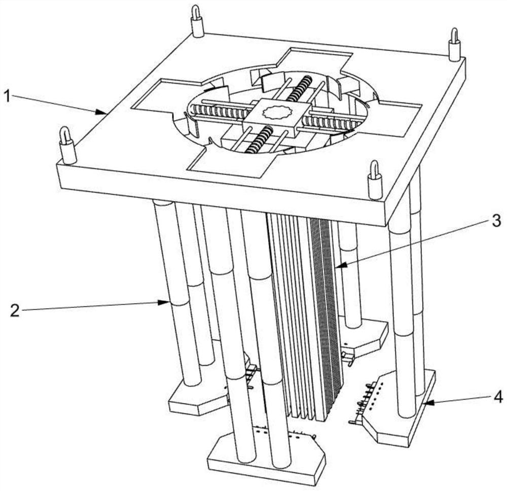
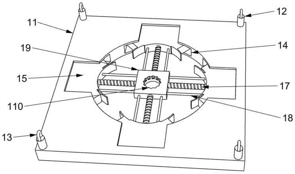
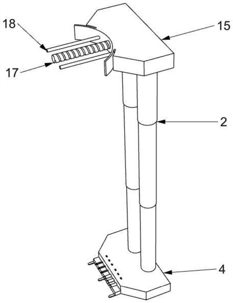
[0030] see Figure 1-6 , in an embodiment of the present invention, an automatic binding device for structural column steel bars for house construction projects includes a driving seat 1, and the driving seat 1 includes a base 11, a fixing seat 12, a rope bolt 13, a built-in chute 14, and a sliding female seat 15. Drive screw 17, slide bar 18, fixed plate 19 and limit gear hole 110;

[0031] The upper end of the base 11 is fixedly installed with a fixed seat ...


PUM


Abstract

The invention discloses a constructional column steel bar automatic binding device for house building engineering. The binding device comprises a driving seat, the driving seat comprises a base, fixing seats, rope lugs, built-in sliding grooves, a sliding female seat, driving lead screws, sliding rods, a fixing plate and limiting tooth holes, the fixing seats are fixedly installed at the positions, close to the four corners, of the upper end of the base, the rope lugs are fixedly installed at the upper ends of the fixing seats, the fixing plate is arranged on the base, the limiting tooth holes are formed in the middle of the upper end of the fixing plate, the four built-in sliding grooves are annularly formed in the circumferential side of the fixing plate, each driving lead screw is arranged in the middle of each built-in sliding groove, and the sliding rods are symmetrically arranged on the left side and the right side of each driving lead screw. When the binding device is used, the binding device is fixedly installed at the lower end of the driving seat through tooth position clamping of a limiting tooth base and a limiting tooth hole and tooth pattern fixing of the limiting tooth base and a bolt block, corresponding adjustment and replacement can be conveniently conducted on different types of steel bar column cages, and meanwhile installation, disassembly and use are convenient.

Description

technical field [0001] The invention relates to a binding device, in particular to an automatic binding device for structural column steel bars used in house construction engineering. Background technique [0002] Traditionally, when building a reinforcement cage, it is first necessary to manually maintain the positions of the stirrups and the longitudinal reinforcements, and then bind the stirrups and the longitudinal reinforcements to obtain the reinforcement cage. The binding operation process is relatively difficult and cumbersome to operate, resulting in low manufacturing efficiency of the reinforcement cage. [0003] At present, manual binding is generally the main method. The problems of manual binding are heavy workload, low efficiency, and certain damage to the human body. Therefore, those skilled in the art provide an automatic binding device for structural column reinforcement used in house construction projects to solve the problems raised in the background tech...

Claims


Application Information

Patent Timeline
Patent Type & Authority Applications(China)
IPC IPC(8): E04G21/12
CPCE04G21/123
Inventor 张学红
Owner 张学红
Learn More