Orchard pesticide spraying robot with anti-bumping moving mechanism
A moving mechanism, anti-bump technology, used in gardening, devices for catching or killing insects, tire treads/tread patterns, etc. Poor protection performance and other problems, to achieve the effect of improving the overall protection performance, improving the anti-bump effect, and preventing overturning
- Summary
- Abstract
- Description
- Claims
- Application Information
AI Technical Summary
Problems solved by technology
Method used
Image
Examples
Embodiment 1
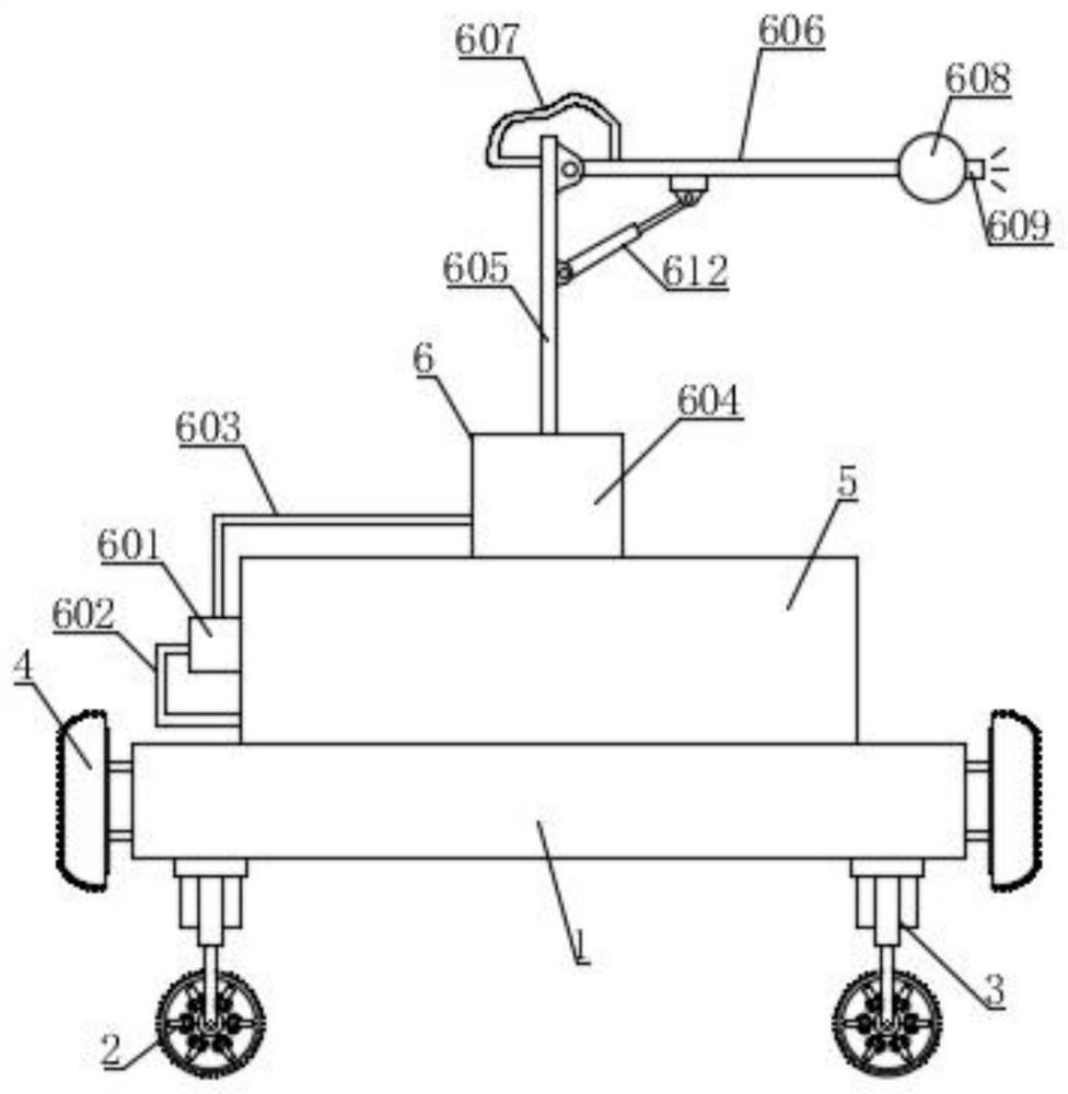
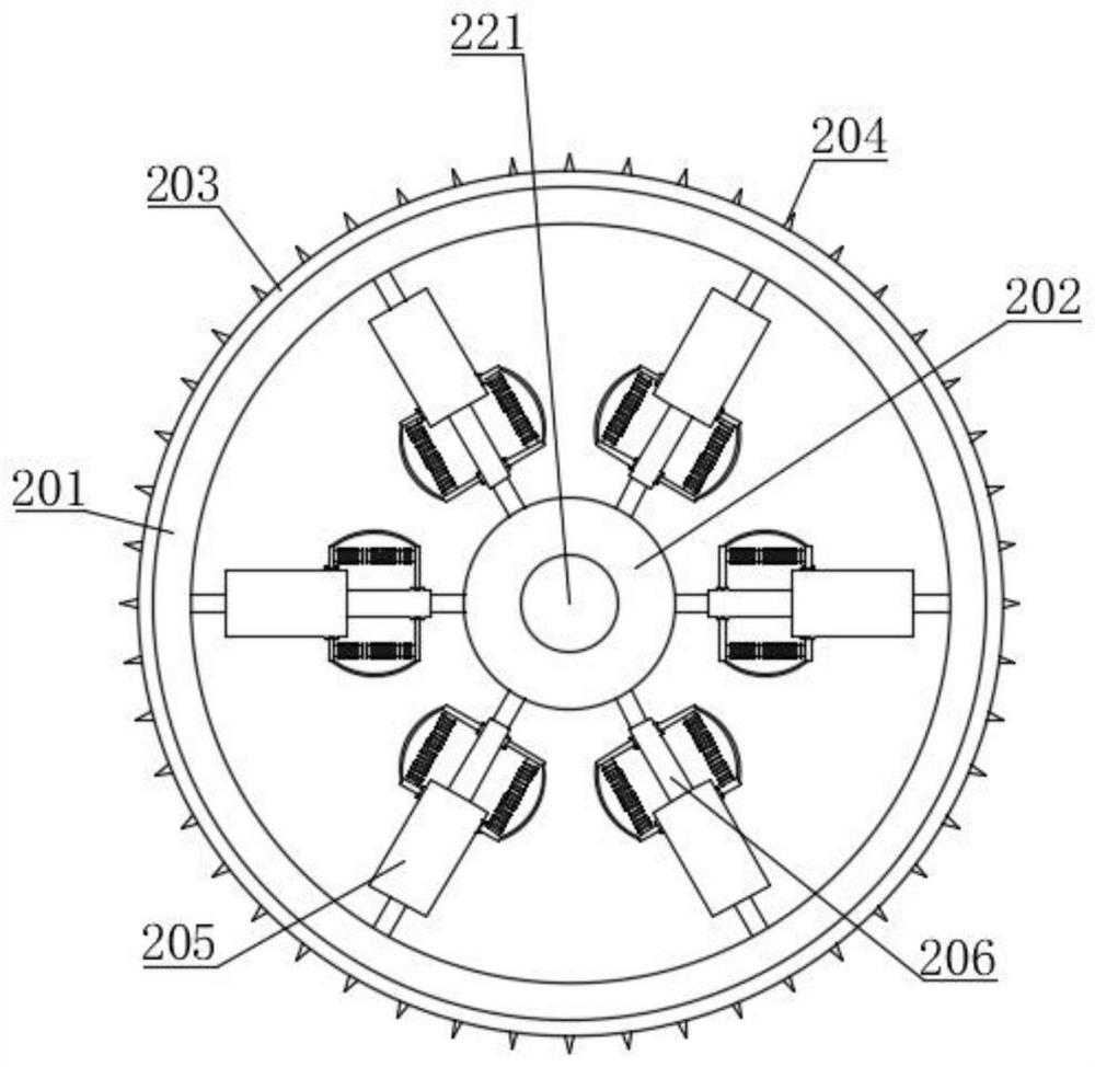
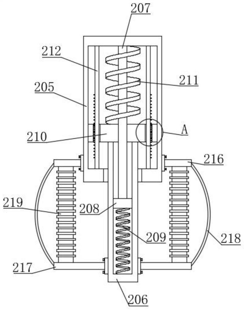
[0045] Such as Figure 1-9 As shown, a kind of orchard pesticide spraying robot with anti-turbulence moving mechanism proposed by the present invention includes a bearing base 1, a medicine storage box 5 and a medicine delivery spraying assembly 6, and the medicine storage box 5 is fixedly installed on the bearing base 1 by bolts , the medicine infusion spray assembly 6 is arranged on the medicine storage box 5, and the medicine infusion spray assembly 6 includes a medicine infusion pump 601, a medicine pumping pipe 602, a medicine infusion pipe 603, a connection box 604, a vertical pipe 605, a connection pipe 606, and a hose 607 , dispersing pipe 608, spraying head 609 and the first cavity 610, the connection box 604 is fixedly installed on the top of the medicine storage box 5 by bolts, the first cavity 610 is opened in the connection box 604, and the drug delivery pump 601 is installed in the storage box 5. On the side wall of the medicine box 5, the drug delivery pump 601 ...
Embodiment 2
[0049] Such as figure 1 and Figure 6 As shown, the difference between this embodiment and Embodiment 1 is that a second cavity 611 is opened in the connection box 604, the second cavity 611 is located above the first cavity 610, and the vertical pipe 605 is rotatably connected with the connection box 604. In the second cavity 611, a motor 613 is fixedly installed through a motor base. The output end of the motor 613 is provided with a second gear 614. The motor 613 is used to drive the second gear 614. The vertical pipe 605 is equipped with a third gear 615. The gear 614 and the third gear 615 are located in the second cavity 611 and engaged in transmission connection; the connecting pipe 606 is rotationally connected with the vertical pipe 605, and the electric push rod 612 is installed on the vertical pipe 605, and the other end of the electric push rod 612 is connected with the connecting pipe 606 connection, when in use, start the motor 613, the motor 613 makes the secon...
Embodiment 3
[0051] Such as Figure 10-11 As shown, the difference between this embodiment and Embodiment 1 and Embodiment 2 is that two sets of anti-collision assemblies 4 are installed on the bearing seat 1, and the anti-collision assemblies 4 are located on both sides of the bearing seat 1, and the anti-collision assemblies 4 include elastic Buffer plate 401, pressure bearing plate 404, fixed column 405, movable rod 406, limit rod 407, second connecting rod 408, movable ring 409, fourth spring 410, fixed column 405 are fixedly installed on bearing seat 1, fixed column The other end of 405 is fixedly connected with the pressure bearing plate 404, the pressure bearing plate 404 is located between the elastic buffer plate 401 and the bearing seat 1, and two sets of elastic buffer plates 401 cover the two sides of the bearing base 1 to prevent the bearing seat from moving during the movement. The two sides of 1 are directly impacted, and the inner wall of the elastic buffer plate 401 is fix...
PUM
 Abstract
Description
Claims
Application Information
 - R&D
- Intellectual Property
- Life Sciences
- Materials
- Tech Scout
- Unparalleled Data Quality
- Higher Quality Content
- 60% Fewer Hallucinations
Browse by: Latest US Patents, China's latest patents, Technical Efficacy Thesaurus, Application Domain, Technology Topic, Popular Technical Reports.
© 2025 PatSnap. All rights reserved.Legal|Privacy policy|Modern Slavery Act Transparency Statement|Sitemap|About US| Contact US: help@patsnap.com


