
Novel spline shaft upsetting forging die structure

A spline shaft and upsetting technology, which is applied to forging/pressing/hammer devices, forging/pressing/hammering machinery, mechanical equipment, etc., can solve the problems of low production efficiency, time-consuming and labor-intensive, etc., and improve the overall efficiency and improve efficiency , to ensure the effect of vertical force

Pending Publication Date: 2021-10-15
WANXIANG QIANCHAO TRANSMISSION SHAFT +1
View PDF0 Cites 0 Cited by
  • Summary
  • Abstract
  • Description
  • Claims
  • Application Information

AI Technical Summary

Problems solved by technology

After the workers use the upsetting die to complete the local deformation of the billet, since there is no ejection device on the rod, it takes time and effort to take it out manually. During the operation, they hold the pliers with their hands, use the outer circle of the upsetting die as the support point, and use the principle of leverage. When prying out, because the force of the pliers is not perpendicular to the direction of the blank, only about 500 blanks can be made in each shift by manual hard pulling, and the production efficiency is low.

Method used


Image

  • Novel spline shaft upsetting forging die structure
  • Novel spline shaft upsetting forging die structure
  • Novel spline shaft upsetting forging die structure

Examples


Embodiment

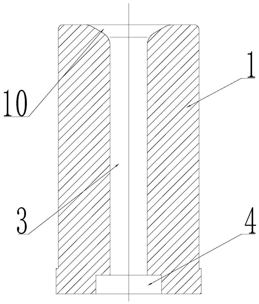
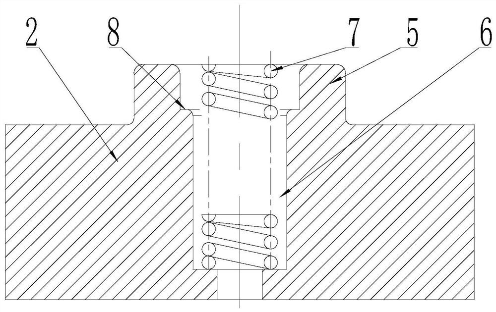
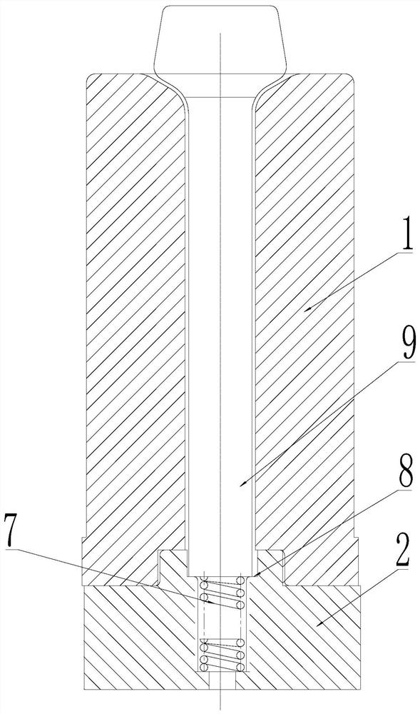
[0013] Embodiment: As shown in the accompanying drawings, this new type of spline shaft upsetting forging die structure is used to pier a blank 9, one end of the blank 9 is a rod 9-1, and the other end of the blank 9 is a pier Part 9-2, the structure includes an upset upper die 1 and a pier lower die 2. Such as figure 1 As shown, a blank passage 3 is provided through the upper die 1 for upsetting, and the inner diameter of the bottom of the blank passage 3 expands to form a concave interface 4; as figure 2 As shown, the top of the pier thick lower die 2 is provided with a convex interface 5 corresponding to the concave interface 4, and the convex interface 5 and the concave interface 4 are embedded and matched so that the upsetting upper die 1 is supported on the pier thick lower die 2; The interface 5 is provided with a spring groove 6 for inserting the spring 7, and the inner wall of the top end of the spring groove 6 is provided with a step surface 8, and the rod portion ...


PUM


Abstract

The invention discloses a novel spline shaft upsetting forging die structure and relates to the field of spline shaft machining. The novel spline shaft upsetting forging die structure comprises an upsetting upper die and an upsetting lower die, a blank channel is arranged in the upsetting upper die in a penetrating mode, the inner diameter of the bottom of the blank channel is expanded to form a concave connector, a convex connector is arranged at the position, corresponding to the concave connector, of the top of the upsetting lower die, the convex connector is matched with the concave connector in an embedded manner, and the upsetting upper die is supported on the upsetting lower die. A spring groove is formed in the convex connector and used for containing a spring, a step face is arranged on the inner wall of the top end of the spring groove, the rod part of a blank is inserted into the blank channel and abuts against the step face, and the upsetting portion of the blank is exposed out of the upper portion of the blank channel. One end of the spring abuts against the bottom of the spring groove, and the other end of the spring abuts against the end face of the rod part, so that the blank moves up and down along the blank channel. The novel spline shaft upsetting forging die structure has the beneficial effects that the ejection vertical force is guaranteed, the material taking efficiency is improved, and the overall spline shaft upsetting efficiency is doubled.

Description

technical field [0001] The invention relates to the field of spline shaft processing, in particular to a novel spline shaft upsetting forging die structure. Background technique [0002] In the existing spline shaft processing technology, local heating is usually used, and the rod is not heated. The diameter of the shaft of the spline shaft is the diameter of the steel, and the big head (end) is the deformed part, which takes part in the deformation and needs to be heated to 1050-1200°C. When the upsetting ratio is greater than 3, an upsetting forging die needs to be designed. After the workers use the upsetting die to complete the local deformation of the billet, since there is no ejection device on the rod, it takes time and effort to take it out manually. During the operation, they hold the pliers with their hands, use the outer circle of the upsetting die as the support point, and use the principle of leverage. When prying out, because the force of the pliers is not per...

Claims


Application Information

Patent Timeline
Patent Type & Authority Applications(China)
IPC IPC(8): B21J13/02B21K1/06
CPCB21J13/02B21K1/066
Inventor 戚利明倪金传
Owner WANXIANG QIANCHAO TRANSMISSION SHAFT
Learn More