Full-automatic test tube cap removing device

A fully automated test tube capping technology, which is applied in packaging, transportation and packaging, and the type of packaged items, can solve the problems of time-consuming, labor-intensive, unguaranteed, and inability to ensure that the test tube cap is corrected, and achieve the effect of saving the time of opening the cap

Inactive Publication Date: 2021-10-15
长沙千麦医学检验实验室有限公司
View PDF0 Cites 0 Cited by
  • Summary
  • Abstract
  • Description
  • Claims
  • Application Information

AI Technical Summary

Problems solved by technology

[0002] In the process of test tube sampling, the test tube cap is first opened, and the test tube cap is changed after adding the reagent. At present, the caps of the test tubes filled with reagents are manually capped one by one, which is time-consuming and labor-intensive. In large quantities, one by one The cap cannot guarantee that the test tube cover is completely changed, and it will pollute the reagents in the test tube when it is placed for a long time. In addition, the personnel in the process of adding reagents cannot ensure that the operation is carried out in a sterile environment, and it is also easy to contaminate the reagents. The present invention designs a fully automatic test tube cap removal device, which can automatically remove the test tube cover and cover test tube cover, and can also complete a fully automatic test tube cap removal device that automatically adds reagents

Method used


Image

  • Full-automatic test tube cap removing device
  • Full-automatic test tube cap removing device
  • Full-automatic test tube cap removing device

Examples


specific Embodiment approach

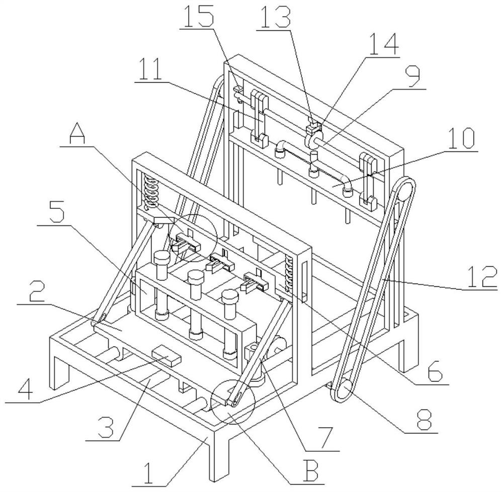
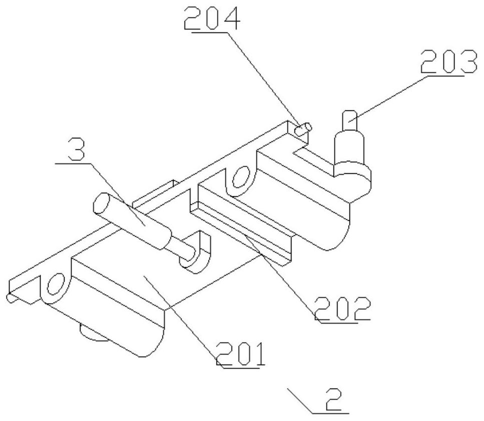
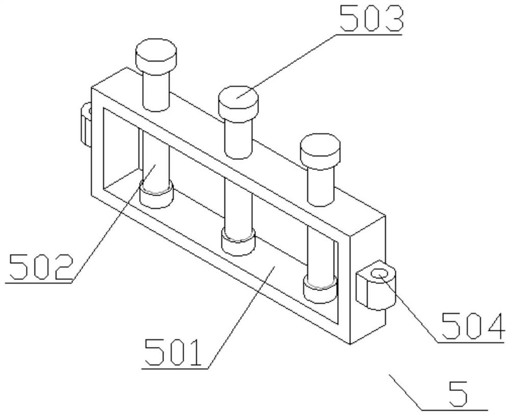
[0030] Combine below Figure 1-9 Describe the specific embodiment of the present invention, a fully automatic test tube cap removal device, including a support mechanism 1, a slide mechanism 2 horizontally slidably connected to the support mechanism 1, and a gripper vertically slidably connected to the support mechanism 1 Mechanism 6 and liquid filling mechanism 10, power storage mechanism 8 connected to the bottom of said support mechanism 1, and transmission mechanism 9 located on the upper side of said liquid filling mechanism 10 and connected to support mechanism 1 in rotation, mounted on said sliding mechanism 2 There is a fixing mechanism 5, the sliding mechanism 2 and the gripping mechanism 6 are connected through a first connecting rod 7, a spring is arranged between the gripping mechanism 6 and the supporting mechanism 1, and the power storage mechanism 8 is connected to the transmission mechanism 9 through a belt 12, the sliding mechanism 2 is meshed with the power s...


PUM


Abstract

The invention discloses a full-automatic test tube cap removing device. The device comprises a supporting mechanism, a sliding mechanism, a clamping mechanism, a liquid adding mechanism, a force storage mechanism and a transmission mechanism, wherein the sliding mechanism is horizontally and slidably connected to the supporting mechanism, the clamping mechanism and the liquid adding mechanism are vertically and slidably connected to the supporting mechanism, the force storage mechanism is connected to the bottom of the supporting mechanism, the transmission mechanism is located on the upper side of the liquid adding mechanism and is rotatably connected to the supporting mechanism, a fixing mechanism is arranged on the sliding mechanism, the sliding mechanism is connected with the clamping mechanism through a first connecting rod, the sliding mechanism is connected with the force storage mechanism in a meshed mode, and the transmission mechanism is connected with the liquid adding mechanism through a second connecting rod. Through mutual cooperation of all the mechanisms, the test tube cap is removed in the moving process, liquid adding is conducted through the liquid adding mechanism after the test tube cap is moved to the end point, the test tube cap can be covered in the process of returning to the original position, and automatic treatment of the whole process of test tube cap removing, liquid adding and cap covering is achieved.

Description

technical field [0001] The invention belongs to the technical field of test tube cap removal devices, in particular to a fully automatic test tube cap removal device. Background technique [0002] In the process of test tube sampling, the test tube cap is first opened, and the test tube cap is changed after adding the reagent. At present, the caps of the test tubes filled with reagents are manually capped one by one, which is time-consuming and labor-intensive. In large quantities, one by one The cap cannot guarantee that the test tube cover is completely changed, and it will pollute the reagents in the test tube when it is placed for a long time. In addition, the personnel in the process of adding reagents cannot ensure that the operation is carried out in a sterile environment, and it is also easy to contaminate the reagents. The present invention designs a fully automatic test tube cap removal device, which can automatically remove the test tube cap and cover the test tub...

Claims


Application Information

Patent Timeline
Patent Type & Authority Applications(China)
IPC IPC(8): B65B43/40B65B7/28B65B3/26
CPCB65B43/40B65B7/28B65B3/26
Inventor 胡芝兰
Owner 长沙千麦医学检验实验室有限公司
Why Eureka
Try Eureka