Rotatable and foldable seat pocket structure and baby carriage applying structure

A seat pocket and rotary button technology, applied in the field of foldable baby carriages, can solve the problem that the seat of the baby carriage cannot be flexibly adjusted and folded, and achieve the effects of convenient outdoor use and adjustment, comfortable posture, and simple adjustment steps.

Pending Publication Date: 2021-10-19
ANHUI COOL BABY SCI & TECH DEV CORP
View PDF0 Cites 0 Cited by
  • Summary
  • Abstract
  • Description
  • Claims
  • Application Information

AI Technical Summary

Problems solved by technology

[0005] The object of the present invention is to propose a rotatable and foldable seat pocket structure and a stroller using this structure in order to solve the problem that the seat of the stroller cannot be flexibly adjusted and the folding area occupies a large area.

Method used


Image

  • Rotatable and foldable seat pocket structure and baby carriage applying structure
  • Rotatable and foldable seat pocket structure and baby carriage applying structure
  • Rotatable and foldable seat pocket structure and baby carriage applying structure

Examples


Embodiment 1

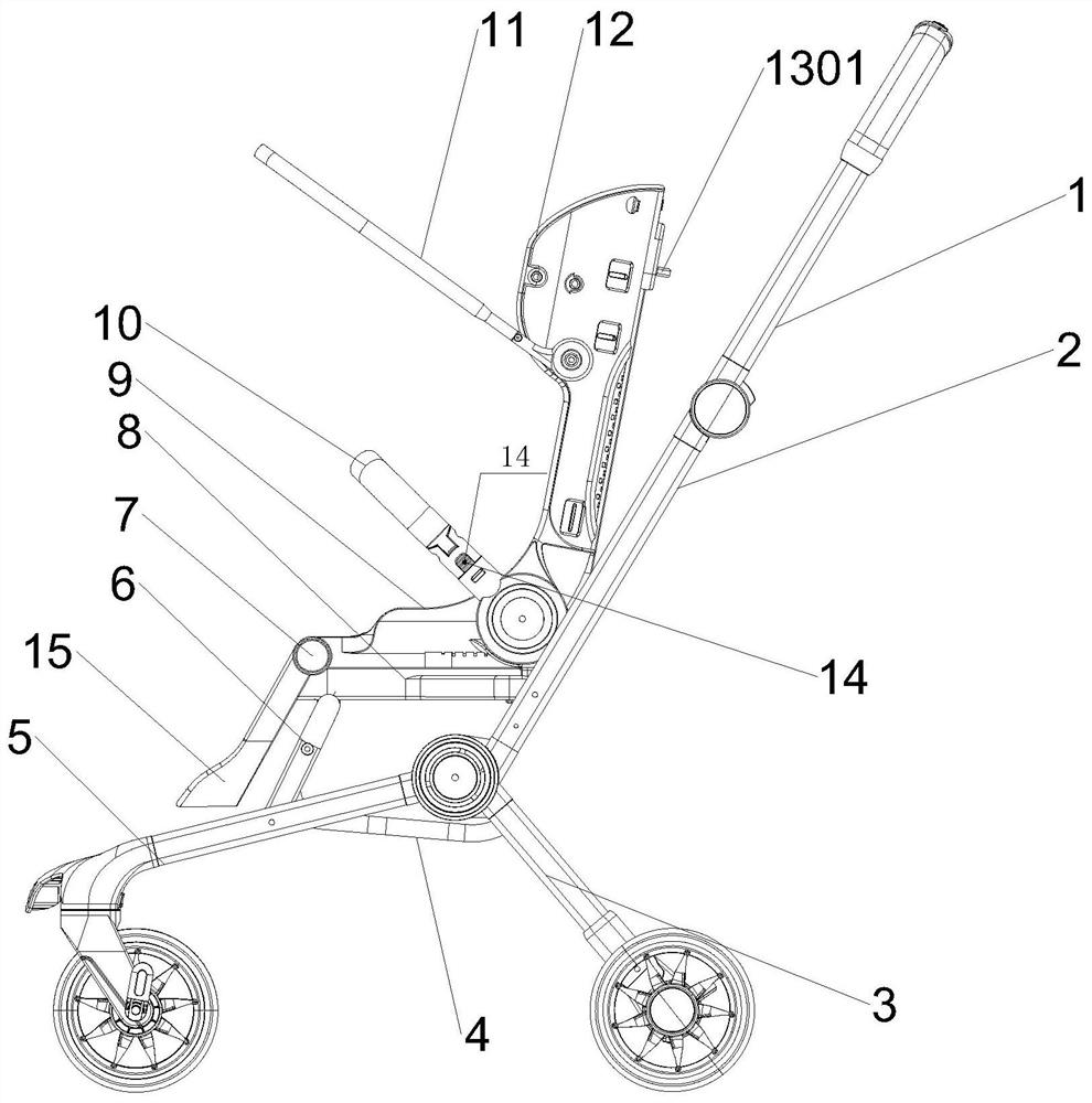
[0034] see Figure 1-Figure 10 As shown, a rotatable and foldable seat pocket structure includes a seat set 9 and an armrest set 10. The armrest set 10 is fixedly connected to the outer wall of the backrest rotation button 103 through the armrest quick-release button 14 to protect the seat set. 9 children in the interior, one end of the seat group 9 is movably connected with a backrest group 12, and the upper part of the backrest group 12 is connected with the canopy group 11 through the rotation of the canopy rotation knob 102, and the canopy group 11 can rotate freely on the backrest group 12 to adjust the canopy. Packed and unfolded, the lower surface of the seat group 9 is rotated and installed with the seat chassis group 8;

[0035]The seat chassis group 8 includes a lower chassis 801 and an upper chassis 802. The upper chassis 802 is slidably connected to the upper surface of the lower chassis 801 for supporting the seat group 9 and controlling the position and movement ...

Embodiment 2

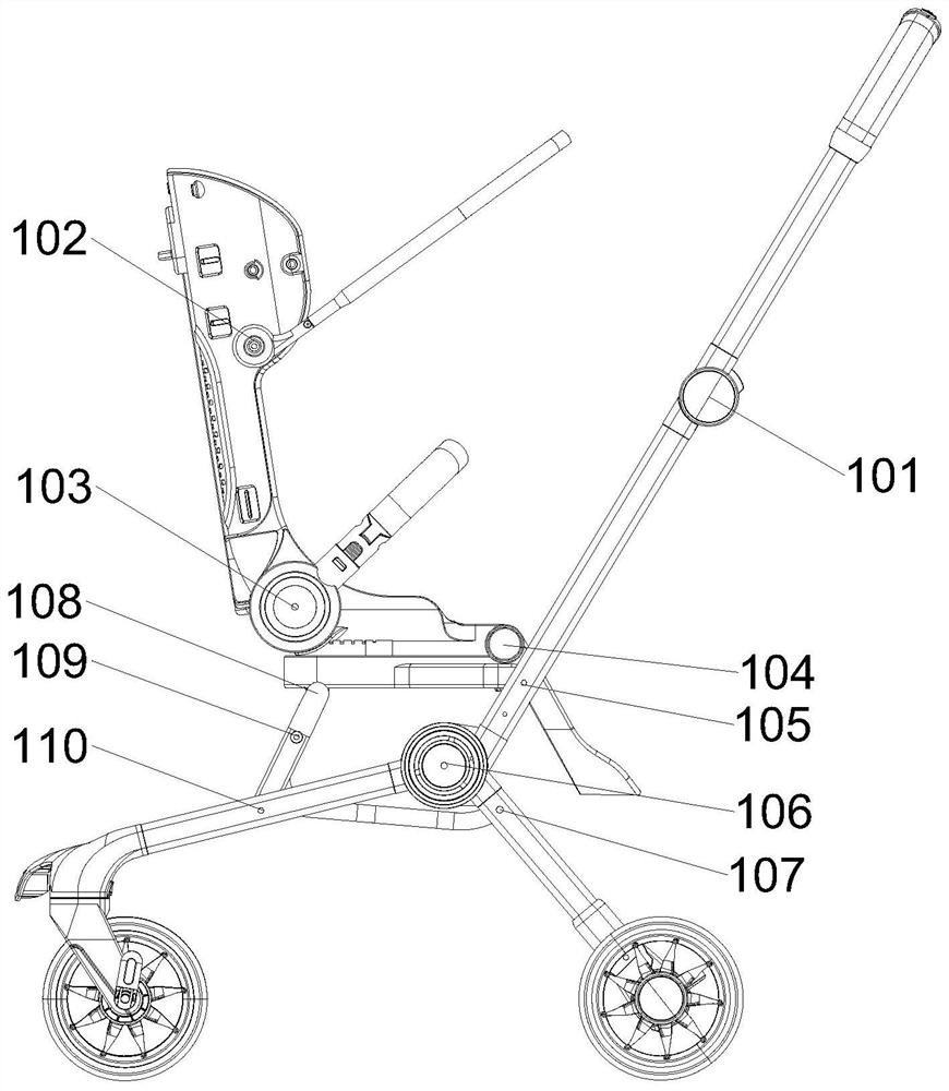
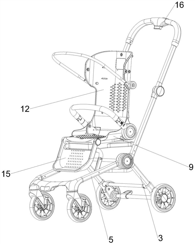
[0037] see Figure 8-Figure 9 As shown, the seat adjustment mechanism 18 includes a gear 1801, a push plate 1802, a block 1803, a seat slot 1804 and a base slot 1805. The gear 1801 is rotatably connected to the inside of the pedal rotary knob 104. The teeth on the gear 1801 are The side is inclined, so that it is convenient to drive the pedal group 15 to rotate when the pedal adjustment button 7 is pressed. The push plate 1802 is embedded in the lower surface of the seat group 9, and the push plate 1802 can slide back and forth on the lower surface of the seat group 9. One end of the plate 1802 is engaged with the gear 1801. When the push plate 1802 moves, it is controlled by the gear 1801. When the gear 1801 rotates, the push plate 1802 can be pushed. The other end of the push plate 1802 contacts the block 1803, and the push plate 1802 The place in contact with the block 1803 is an inclined surface. When the push plate 1802 slides, the block 1803 is squeezed by the wedge-shap...

Embodiment 3

[0039] see Figure 11 As shown, the backrest adjustment mechanism 13 includes a backrest retractable handle 1301, a backrest bayonet 1302 and a backrest bayonet groove 1303, wherein the structure of the backrest bayonet 1302 is basically the same as that of the translation bayonet 19. The elastic support is realized for the clamping column in the bayonet to ensure the extension of the front end of the bayonet in the natural state, and to realize the function of engagement. The backrest retractable handle 1301 is slidably connected to the side of the backrest group 12, and this side is located on the upper push handle group. 1, it is convenient for the pusher to pull the backrest retractable handle 1301. The backrest group 12 is located below the backrest retractable handle 1301 and has a wiring groove, and a traction line is embedded in the wiring groove, and one end of the traction line is folded with the backrest. The pull handle 1301 is connected, and the other end of the t...


PUM


Abstract

The invention relates to a foldable baby carriage technology, aims to solve the problems that a seat pocket of a baby carriage cannot be flexibly adjusted and the folded seat pocket occupies a large area, and particularly relates to a rotatable and foldable seat pocket structure and a baby carriage applying the structure. The structure comprises an upper push handle group, a lower push handle group, a rear foot group, a linkage rod, a front foot group, a seat bag supporting rod, a seat bag chassis group, a seat bag group, an armrest group, an awning group, a backrest group and a pedal group; in the invention, when the seat bag group is adjusted, the seat bag group can be rotated by pressing the pedal adjusting button to rotate the pedal upwards, so that the seat bag group rotates above the seat bag chassis group and rotates backwards, and then the pedal group is put down to a drooping state to complete the adjustment of the seat bag group, the direction of the seat bag can be adjusted as required, comfort for the child in riding is increased, meanwhile, the step of adjusting the direction of the sitting bag is also very simple, even if the child is held by one hand, the other hand can also easily operate, and outdoor use and adjustment of parents are facilitated.

Description

technical field [0001] The invention relates to foldable stroller technology, in particular to a rotatable and foldable seat pocket structure and a stroller using the structure. Background technique [0002] Baby stroller is a tool cart designed to provide convenience for babies' outdoor activities. It is also the baby's favorite means of transportation for walking, and it is also a necessity when mothers take their babies to the street for shopping. There are many types, mainly based on the load capacity, the general test standard is nine to fifteen kilograms, and the general baby carriage can be used for about four to five years; [0003] At present, there are still deficiencies in the existing baby carriages. When most baby carriages are in use, they often cannot be folded or only have a simple folding function, which cannot compress the volume of the baby carriage more thoroughly. , occupies a large volume and is not convenient for storage; in addition, although some fr...

Claims


Application Information

Patent Timeline
Patent Type & Authority Applications(China)
IPC IPC(8): B62B7/06B62B9/10B62B9/12
CPCB62B7/06B62B9/102B62B9/12
Inventor 张迎年孔凡龙
Owner ANHUI COOL BABY SCI & TECH DEV CORP
Why Eureka
Try Eureka