Self-balancing container

A self-balancing, container technology, applied in the field of containers, can solve the problems of no buffer function and damaged goods, and achieve the effect of enhancing the magnetic field force

Pending Publication Date: 2021-10-19
赵平
View PDF0 Cites 0 Cited by
  • Summary
  • Abstract
  • Description
  • Claims
  • Application Information

AI Technical Summary

Problems solved by technology

[0005] The purpose of the present invention is to provide a self-balancing container for the above-mentioned problems that most of the existing containers do not have a buffer function, and the internal goods are easily squeezed with the box body to cause damage to the goods when they encounter a collision.

Method used


Image

  • Self-balancing container
  • Self-balancing container

Examples


Embodiment 1

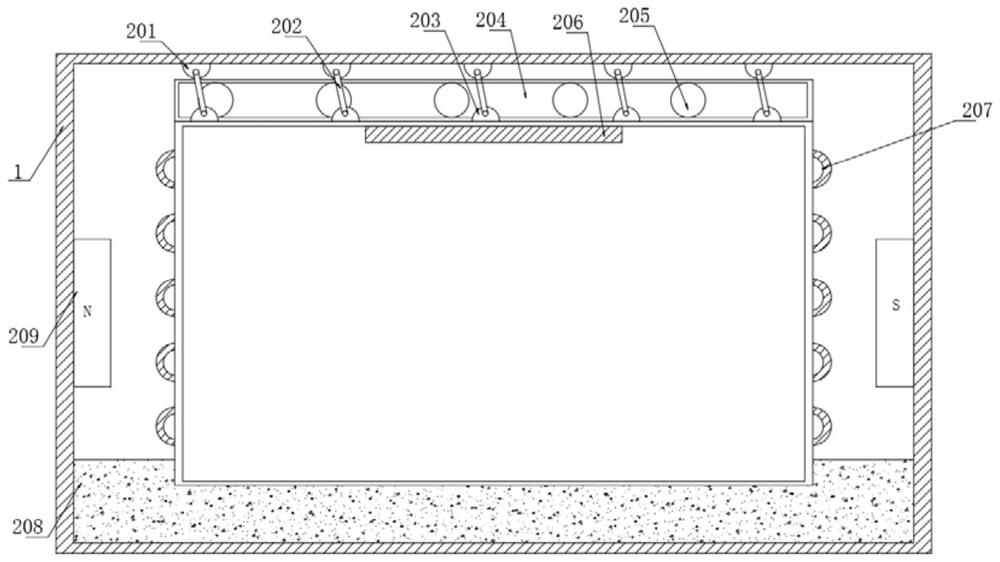
[0019] Such as figure 1 As shown, a self-balancing container includes an outer box body 1, an inner box body 11 is movably installed in the inner cavity of the outer box body 1, and a braking mechanism 2 is fixedly installed in the inner cavity of the outer box body 1, and the braking mechanism 2 Including the top base 201, the bottom surface of the top base 201 is fixedly connected with a steel cable 202, the end of the steel cable 202 away from the top base 201 is fixedly connected with a base 203, the top surface of the inner box 11 is fixedly installed with a buffer 204, and the buffer 204 A number of buffer balls 205 are movable in the inner cavity, piezoelectric ceramics 206 are fixedly installed on the top surface of the inner cavity of the inner box body 11, and several turn groups 207 are uniformly wound on the surface of the inner box body 11, and the inner cavity of the outer box body 1 The bottom surface is filled with fine sand 208, and the side of the inner cavit...

Embodiment 2

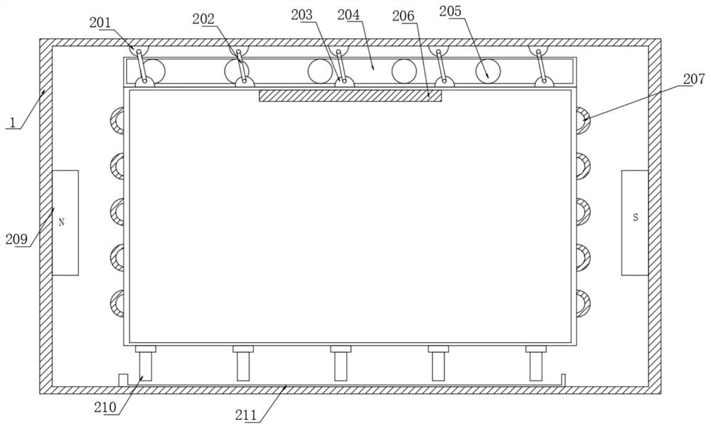
[0027] Such as figure 2 As shown, the difference between this embodiment and Embodiment 1 is: the bottom surface of the inner box body 11 is evenly distributed and fixedly connected with several steel rods 210, the top surface of the inner cavity of the outer box body 1 is fixedly equipped with slide rails 211, and the steel rods The end of 210 away from the bottom surface of the inner box 11 is slidably socketed on the top surface of the slide rail 211, and the top of the steel rod 210 is electrically connected with the line group 207, so that when the inner box 11 performs emergency braking, the steel rod 210 can The surface of the slide rail 211 slides, thereby cutting the magnetic induction lines and generating induced currents;

[0028] And the magnitude of the induced electromotive force in the circuit is proportional to the magnitude of the induced electromotive force in the circuit and the rate of change of the magnetic flux passing through this circuit, that is If ...


PUM


Abstract

The invention belongs to the field of containers, and particularly relates to a self-balancing container which comprises an outer container body and a brake mechanism. The outer container body comprises an inner container body, and the brake mechanism comprises top seats, steel cables, bottom seats, a buffer, buffer balls, a piezoelectric ceramic element, a wire set, fine sand, bar permanent magnets, steel bars and a sliding rail. In the sliding process of the buffer balls, a pressure change is formed on the piezoelectric ceramic element fixedly installed on the top face of an inner cavity of the inner container body, and then induced current is generated; the piezoelectric ceramic element is fixedly connected with the wire set, so that the induced current generated by the piezoelectric ceramic element enters the wire set, and then the wire set generates a magnetic field; in the emergency braking process of the outer container body, the fine sand and the buffer balls have an inertia difference due to the mass difference of the fine sand and the buffer balls; and when the buffer balls are concentrated at one end of the top face of the inner container body, one end of the inner container body moves downwards, then the fine sand is supplemented to the bottom face of the downward moving end of the inner container body due to inertia, and thus the effect of keeping a self-balancing state in the inner container body is achieved.

Description

technical field [0001] The invention belongs to the field of containers, in particular to a self-balancing container. Background technique [0002] The property of an object to remain at rest or in a state of uniform linear motion is called inertia. Inertia is an inherent property of an object, which is expressed as a degree of resistance of the object to changes in its motion state. Mass is a measure of the inertia of an object. Since the container needs to load a large amount of goods, its own inertia will greatly increase. When encountering a collision It is easy to cause damage to the internal goods. [0003] The problem that still exists is that most of the current containers do not have a buffer function, and the internal goods are easily squeezed with the box body when encountering a collision, causing the goods to be damaged. [0004] For this reason, we propose a self-balancing container to solve the above problems. Contents of the invention [0005] The purpos...

Claims


Application Information

Patent Timeline
Patent Type & Authority Applications(China)
IPC IPC(8): B65D90/00
CPCB65D90/004B65D90/00
Inventor 赵平
Owner 赵平
Why Eureka
Try Eureka