
Device for improving display effect of LED display screen and using method of device

A technology of LED display screen and display effect, applied in the direction of identification devices, instruments, supporting machines, etc., can solve the problems of inability to effectively improve the display effect of the display screen group, without black edge elimination, and reducing the use effect of the device. Group screen display effect, improve aesthetics, eliminate glue marks

Inactive Publication Date: 2021-10-22
马鞍山金裕丰电子科技有限公司
View PDF1 Cites 0 Cited by
  • Summary
  • Abstract
  • Description
  • Claims
  • Application Information

AI Technical Summary

Problems solved by technology

[0004] The existing devices for improving the display effect of LED displays have certain disadvantages in the process of use. The traditional devices for improving the display effect of LED displays do not have a black edge elimination structure. When multiple groups of LED displays are assembled and installed, The black border between the two groups of LED displays cannot be eliminated. The traditional device for improving the display effect of the LED display can only adjust the viewing angle of the display, but cannot effectively improve the display effect of the display screen group operation; secondly, the traditional improvement of the LED display The display screen display effect device does not have an auxiliary fixing structure, making it impossible to complete the installation and fixation of multiple sets of display screens at one time, thereby reducing the use effect of the device and bringing certain adverse effects to users

Method used


Image

  • Device for improving display effect of LED display screen and using method of device
  • Device for improving display effect of LED display screen and using method of device
  • Device for improving display effect of LED display screen and using method of device

Examples


Embodiment Construction

[0027] The technical solutions in the embodiments of the present invention will be clearly and completely described below in conjunction with the embodiments of the present invention. Apparently, the described embodiments are only some of the embodiments of the present invention, not all of them. Based on the embodiments of the present invention, all other embodiments obtained by persons of ordinary skill in the art without creative efforts fall within the protection scope of the present invention.

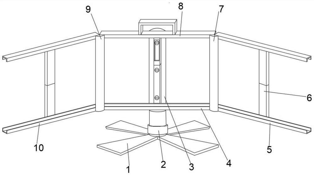
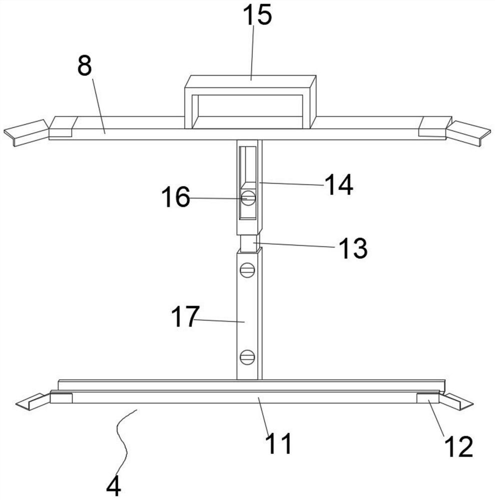
[0028] Such as Figure 1-5 As shown, a device for improving the display effect of the LED display screen includes a first card frame 4, a second card frame 5 and a third card frame 10, and the third card frame 10 is movably installed outside one side of the first card frame 4 On the surface, the second card frame 5 is movably installed on the other side outer surface of the first card frame 4, and the two ends of the first card frame 4 are equipped with rotating card holders 12, t...


PUM


Abstract

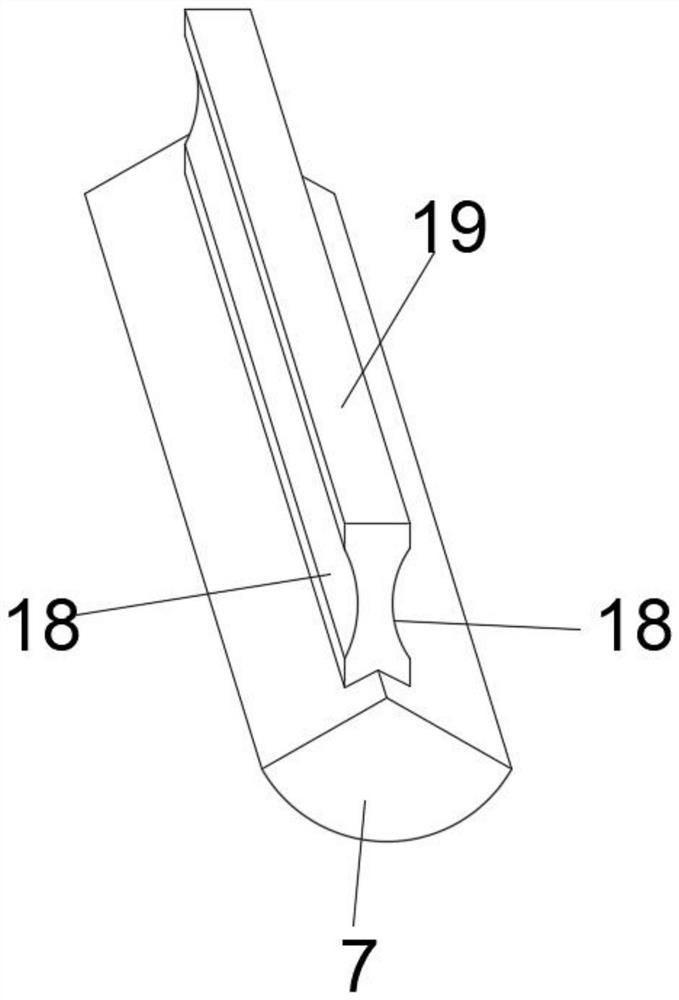
The invention discloses a device for improving the display effect of an LED display screen. The device for improving the display effect of the LED display screen comprises a first clamping frame, a second clamping frame and a third clamping frame, the third clamping frame is movably installed on the outer surface of one side of the first clamping frame, the second clamping frame is movably installed on the outer surface of the other side of the first clamping frame, rotating clamping bases are installed at the two ends of the first clamping frame correspondingly, the second clamping frame, the third clamping frame and the first clamping frame are movably connected through the rotary clamping bases, a first reflective strip is arranged between the second clamping frame and the first clamping frame, a second reflective strip is arranged between the third clamping frame and the first clamping frame, and the outer surfaces of the side edges of the second reflective strip and the first reflective strip are each of an arc-shaped structure; through picture mapping on the first reflective stripe and the second reflective stripe, black edges generated when two groups of display screens are spliced can be effectively eliminated, so that a display effect without the black edges can be achieved when a plurality of groups of displays are subjected to group screen operation, the device is provided with a black edge eliminating structure, and the group screen display effect of the display screens is improved.

Description

technical field [0001] The invention belongs to the technical field of display auxiliary equipment, and more specifically relates to a device for improving the display effect of an LED display screen and a use method thereof. Background technique [0002] The device for improving the display effect of the LED display screen is a device suitable for improving the display effect of the display screen assembly during the installation and operation of the display screen assembly, and the display angle of the display screen can be flexibly adjusted through the device. [0003] Patent document CN205447195U discloses an imaging lens holder for an electric head-up display, including a base and an imaging lens. The base includes an upper cover and a lower cover. The cover is fastened on the closed edge, and a mounting base and a rotating motor are provided on one side of the lower cover. There is a rotating shaft between the seat and the supporting part, and a clamping piece for cla...

Claims


Application Information

Patent Timeline
Patent Type & Authority Applications(China)
IPC IPC(8): F16M11/04F16M11/08F16M11/22G09F9/302
CPCF16M11/04F16M11/08F16M11/22G09F9/302
Inventor 肖戈
Owner 马鞍山金裕丰电子科技有限公司
Learn More