Magnetic force measuring device

A technology of magnetic force measurement and magnetic conduction, applied in the direction of magnetic performance measurement, etc., can solve the problems that the measurement results cannot be obtained, the lifting speed cannot be kept completely consistent, and the spring balance cannot maintain the maximum value, etc., and achieve high practical value.

Pending Publication Date: 2021-10-22
索璞科技(海宁)有限公司
View PDF0 Cites 1 Cited by
  • Summary
  • Abstract
  • Description
  • Claims
  • Application Information

AI Technical Summary

Problems solved by technology

However, in the prior art, when the spring balance is used to directly pull up the test workpiece, due to individual differences, the speed at which each person pulls the test workpiece must be different, and even the same person cannot maintain the same speed at different time points. Consistent, resulting in the use of spring scales to pull up the test workpiece for magnetic force detection, the results obtained vary from person to person and time, and the spring balance cannot be kept at the maximum value, and the most accurate measurement results cannot be obtained

Method used


Image

  • Magnetic force measuring device
  • Magnetic force measuring device
  • Magnetic force measuring device

Examples


no. 1 approach

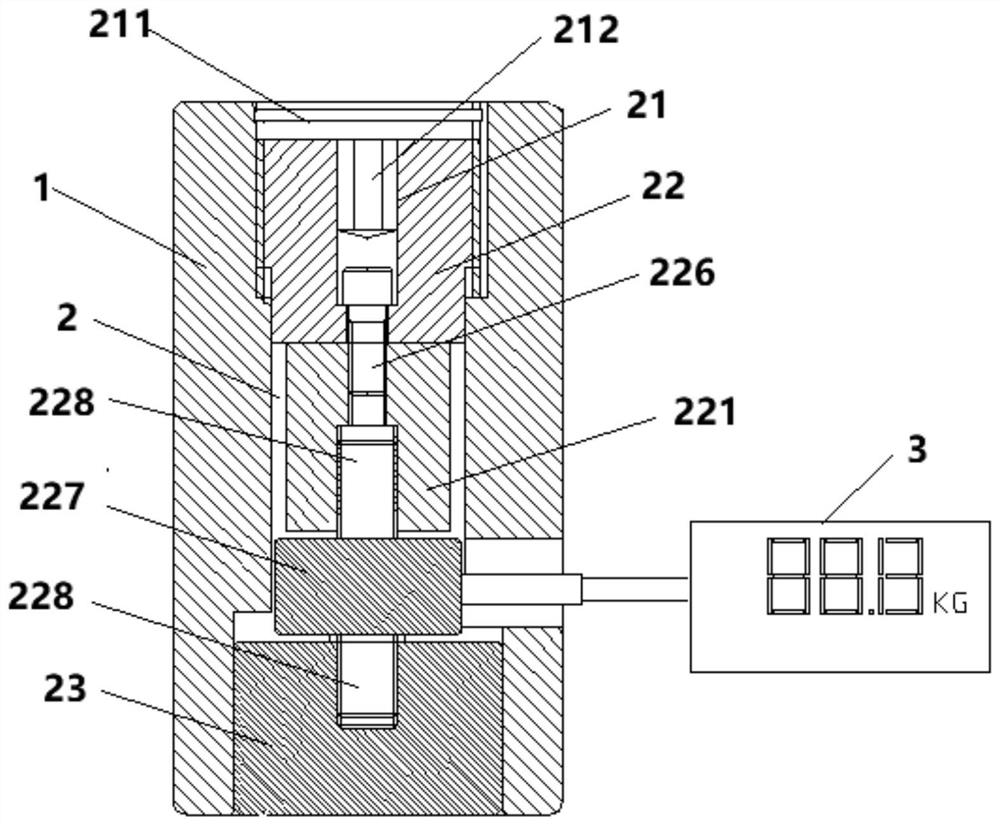
[0029] Such as figure 1 As shown, the first embodiment of the present invention discloses a magnetic measuring device, including a measuring body 1, the center of the measuring body 1 is provided with a longitudinal passage 2 along its axial direction, and the inside of the longitudinal passage 2 is arranged from top to bottom There is a lifting system 21, an intermediate system 22, a top block 23, and a pressure gauge 3 associated with the intermediate system 22. The bottom surface of the measuring body 1 is flush with the bottom surface of the top block 23 and forms the same contact plane that contacts the magnetic module. One of the measuring body 1 and the top block 23 is magnetically conductive, and the other is not magnetically conductive. When the lifting system 21 is subjected to an external force, it can drive the intermediate system 22 to move upward or downward in the longitudinal channel 2 to measure the The top block 23 exerts force to lift up or push the top bloc...

no. 2 approach

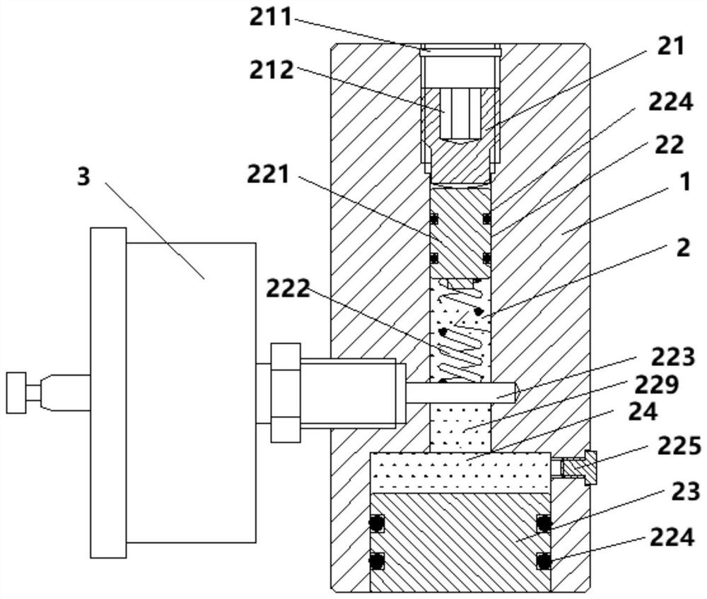
[0043] Such as figure 2 As shown, the second embodiment of the present invention discloses a magnetic measuring device, including a measuring body 1, the center of the measuring body 1 is provided with a longitudinal passage 2 along its axial direction, and the interior of the longitudinal passage 2 is arranged from top to bottom There is a lifting system 21, an intermediate system 22, a top block 23, and a pressure gauge 3 associated with the intermediate system 23. The bottom surface of the measuring body 1 is flush with the bottom surface of the top block 23 and forms the same contact plane that contacts the magnetic module. The measuring body 1 is magnetically conductive, and the top block 23 is not magnetically conductive. When the lifting system 21 is subjected to an external force, it can drive the intermediate system 22 to move upward or downward in the longitudinal channel 2, and the intermediate system 22 moves downward. When pushing the top block 23 to press the up...


PUM


Abstract

The present invention discloses a magnetic force measuring device which comprises a measuring main body, the center of the measuring main body is provided with a longitudinal channel, the longitudinal channel is internally provided with a lifting system, a middle system, a top block and a pressure gauge associated with the middle system from top to bottom, and the bottom surface of the measuring main body and the bottom surface of the top block are flush and form the same contact plane in contact with a magnetic force module. One of the measuring main body and the top block is magnetic-conductive, and the other one is non-magnetic-conductive; When the lifting system is subjected to external acting force, the middle system can be driven to move upwards or downwards in the longitudinal channel so as to apply force to the top block, the top block is lifted upwards or pushed to jack the measuring body upwards, the pressure gauge records the maximum stress value of the top block, and a magnetic force value can be obtained through calculation. According to the invention, the measurement result is not influenced by different operators, time or places, an accurate magnetic measurement value can be obtained, and the method has a very high practical value in practice.

Description

technical field [0001] The invention relates to the field of magnetic force measurement, in particular to a magnetic force measurement device. Background technique [0002] At present, the magnetic module is widely used in various machinery and handling fields. In many scenarios, it is necessary to accurately measure the magnetic force of the magnetic module to meet the needs of the project. Usually, when the magnetic force needs to be measured, it is necessary to use a spring balance to directly pull up the test workpiece. However, in the prior art, when the spring balance is used to directly pull up the test workpiece, due to individual differences, the speed at which each person pulls the test workpiece must be different, and even the same person cannot maintain the same speed at different time points. Consistent, resulting in the use of spring scales to pull up the test workpiece for magnetic force detection, the results obtained vary from person to person and time, and...

Claims


Application Information

Patent Timeline
IPC IPC(8): G01R33/12
CPCG01R33/12
Inventor 丁弘
Owner 索璞科技(海宁)有限公司
Why Eureka
Try Eureka