

Four-direction two-dimensional ankle joint comprehensive reaction time measurement method and system
A measurement system and response time technology, applied in diagnostic recording/measurement, application, medical science, etc., can solve problems such as poor reliability and insufficient data pointing, and achieve comprehensive protection, elimination of system errors, and high application value.
- Summary
- Abstract
- Description
- Claims
- Application Information
AI Technical Summary
Benefits of technology
Problems solved by technology
Method used
Image

Examples
Embodiment 1
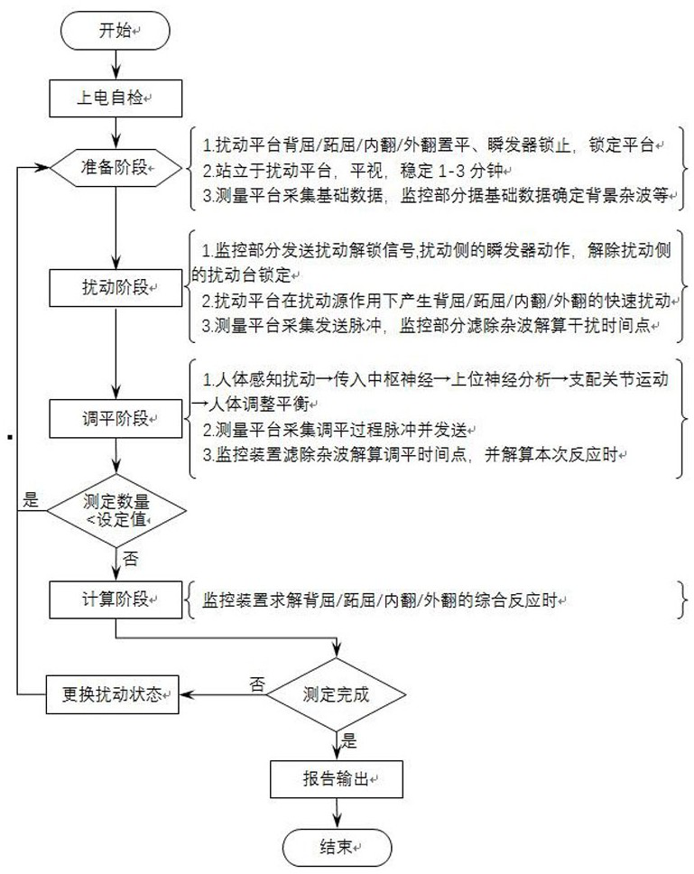
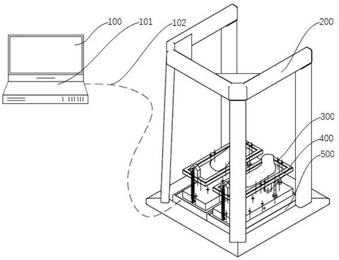
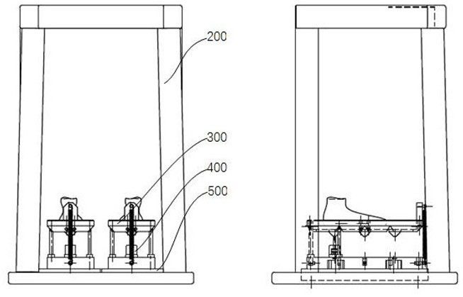
[0024] Step (1) The system is powered on and self-inspected, and the disturbance generator 310, the supporting knife column 330 and the prompt device 400 in the disturbance part 300 are respectively pressed Figure 7 Combination of corresponding installation positions constitutes dorsiflexion / plantarflexion or varus / valgus measurement state;
[0025]Step (2) In the preparatory stage, the disturbance platform 320 is set flat and locked with the prompter 402. The person to be tested stands on the two disturbance platforms 320 with his feet apart, looks straight, and stabilizes for 1-3 minutes. The measurement The platform 500 collects basic data, and the monitoring part 100 determines background clutter, etc. according to the basic data;
[0026] Step (3) In the disturbance stage, the monitoring part 100 sends a disturbance side unlock signal, and the prompter 402 on the disturbance side acts to unlock the disturbance platform on the disturbance side; the disturbance platform 32...
Embodiment 2
[0033] The measurement method of the comprehensive reaction time of both feet of the ankle joint based on the above-mentioned measurement method is as follows: both feet stand respectively on two sets of disturbance platforms 320 of the A side and the B side, both hands are placed on the waist, and one of the A side disturbances The platform 320 exerts dorsiflexion / plantarflexion / varus / valgus disturbance on the ankle joint, and the other B-side disturbance platform 320 is maintained in a horizontal state, and the pulse peak time point and the pulse peak time point of the A-side measurement platform 500 caused by the disturbance are calculated. The time difference of the pulse peak time point of the B-side measurement platform 500 caused by the measurer's adjustment of the balance response is the comprehensive reaction time of dorsiflexion / plantarflexion / varus / valgus of both feet of the ankle joint.
Embodiment 3
[0035] The measurement method of the reaction time of one foot based on the above-mentioned measurement method is: stand on one side of the disturbance platform 320 with one foot, bend the knee on the other side, place both hands on the waist, and the disturbance platform 320 on this side exerts dorsiflexion / plantar flexion on the ankle joint. For the disturbance of flexion / varus / valgus, calculate the time difference between the pulse peak time point of the measurement platform 500 described on this side caused by the disturbance and the time point of the pulse peak time point of the measurement platform 500 described on this side caused by the measurer’s adjustment of balance response, which is Ankle single foot dorsiflexion / plantarflexion / varus / valgus combined response.
[0036] The present invention relates to four to two-dimensional ankle comprehensive response time measurement system figure 2 , 3 , see below for specific implementation.
PUM
 Abstract
Description
Claims
Application Information