
Removable-flask moulding 3D sand mold printing system

A boxless modeling and printing system technology, applied in the field of 3D printing, can solve problems such as low work efficiency, energy waste, and printing errors, and achieve the effects of improving work efficiency, saving energy, and avoiding printing errors

Active Publication Date: 2021-10-26
郑州中兴三维科技有限公司
View PDF15 Cites 0 Cited by
  • Summary
  • Abstract
  • Description
  • Claims
  • Application Information

AI Technical Summary

Problems solved by technology

[0004] The reference application number is CN201911152343.9, and the name of the invention is: a high-precision 3D sand mold printing equipment, which is provided with a sand box, and a lifter frame that can be lifted inside the sand box is provided. layer, and the sand box can limit the sand layer to prevent the sand particles from scattering. After the model is printed, it is lifted by the lifter, and the sand particles that are not bonded by glue are scattered and flowed down, and then the sand particles that are bonded by glue are taken out. The model is enough; however, due to the different sizes of the processed parts, in order to make the 3D printing equipment able to cope with products of different sizes, it is generally necessary to make the sand box large enough, and regardless of the size of the product, it is necessary to cover the entire sand box every time it is printed. The sand box weighs several tons when the sand box is filled with sand, and the lifting frame needs to provide a large lifting force during work, which causes unnecessary waste of energy and low work efficiency. And it is easy to cause the sand box to be deformed when the sand is covered with sand, thus causing printing errors

Method used


Image

  • Removable-flask moulding 3D sand mold printing system
  • Removable-flask moulding 3D sand mold printing system
  • Removable-flask moulding 3D sand mold printing system

Examples


Embodiment 1

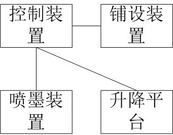
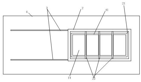
[0037] The present invention provides a boxless 3D sand mold printing system, refer to Figure 1-Figure 4 , as a specific embodiment, including a lifting platform 1 capable of vertical lifting and a bracket 2 arranged above the lifting platform 1, the lifting platform 1 includes a plurality of sub-platforms 1a, each of the sub-platforms 1a All can be lifted up and down independently, and the bracket 2 is provided with a plurality of channels 21 through which the plurality of sub-platforms 1a pass.

[0038] Specifically, by setting the lifting platform, and setting the lifting platform as multiple sub-platforms that can be lifted separately, and setting brackets on the lifting platform, in the actual printing process, the corresponding sub-platforms can be flexibly controlled according to the size of the sand mold. That is, the entire lifting platform does not need to be raised and lowered, thereby saving energy.

[0039] Further, as a preferred embodiment, refer to Figure 2...

Embodiment 2

[0047] Further, this application also provides a reference to the use method of a boxless 3D sand mold printing system Figure 5-Figure 7 , the method includes the following steps:

[0048] Step 1. Reference Figure 5 , placing a carrier plate 8 on the bracket 2;

[0049] Specifically, the carrier plate 8 is a flat plate, which is laid on the carrier plate 8 when laying the sand layer.

[0050] Step 2, controlling the lifting platform 1 to rise, and lifting the carrier plate to a preset height;

[0051] Step 3. Reference Figure 5-Figure 7 , the control device 7 controls the laying device 5 to lay a sand layer of a predetermined size on the carrier plate, (the sand layer of a predetermined size refers to a sand layer of a preset size set according to the size of the sand mold to be printed, and the laying The size of the sand layer can be guaranteed to form the coaming and sand mold mentioned below, so as to reduce the amount of sand grains); and the inkjet device 6 ejects...


PUM


Abstract

The invention provides a removable-flask moulding 3D sand mold printing system which comprises a lifting platform capable of vertically ascending and descending and a bracket arranged above the lifting platform, the lifting platform comprises a plurality of sub-platforms, each sub-platform can independently ascend and descend, and a plurality of channels allowing the sub-platforms to pass through are formed in the bracket; the lifting platform is arranged, the lifting platform is provided with the multiple sub-platforms capable of ascending and descending independently, the bracket is arranged on the lifting platform, the corresponding sub-platforms can be flexibly controlled to ascend and descend according to the size of a sand mold in the actual printing process, the whole lifting platform does not need to ascend and descend, and therefore energy is saved.

Description

technical field [0001] The present invention generally relates to the technical field of 3D printing, in particular to a boxless 3D sand mold printing system. Background technique [0002] The foundry industry is a labor-intensive, high-energy-consumption, and high-pollution industry. The foundry industry needs to focus on research and adoption, promote advanced casting technology and introduce other advanced technologies, seek a combination with advanced technology to change the status quo of the foundry industry, and realize the foundry industry to low energy consumption. , low pollution and high quality. [0003] With the development of 3D printing technology today, its development focus has shifted from 3D printing prototypes to rapid manufacturing and rapid direct manufacturing of metal parts. 3D printing technology is not only used in the design process, but also extends to the manufacturing field. In manufacturing, The main factor that limits the time for products to...

Claims


Application Information

Patent Timeline
Patent Type & Authority Applications(China)
IPC IPC(8): B22C9/02B22C23/00B33Y30/00B33Y10/00
CPCB22C9/02B22C23/00B33Y30/00B33Y10/00
Inventor 刘中兴吴阳
Owner 郑州中兴三维科技有限公司
Learn More