Soot blowing control system and method for heating surface of boiler

A control system and control method technology, applied in the field of boilers, can solve problems such as wear and erosion of heating surface furnace tubes, consumption of high-temperature steam, and consumption of soot-blowing working fluid, so as to achieve accurate and visualized soot blowing, improve soot blowing effect, and slow down Effect of Thin Velocity

Pending Publication Date: 2021-10-26
YANTAI LONGYUAN POWER TECH
View PDF0 Cites 0 Cited by
  • Summary
  • Abstract
  • Description
  • Claims
  • Application Information

AI Technical Summary

Problems solved by technology

During the operation of the boiler, if the soot blowing is performed sequentially, a large amount of high-temperature steam will be consumed; if the soot blower is used too many times, that is, the soot blowing cycle is too short, it will bring unnecessary consumption of soot blowing fluid and The furnace tube on the heating surface is worn and eroded. If the cycle is too long, the soot blowing effect will be poor, and the loss caused by the dust on the heating surface will be too large

Method used


Image

  • Soot blowing control system and method for heating surface of boiler
  • Soot blowing control system and method for heating surface of boiler

Examples


Embodiment 1

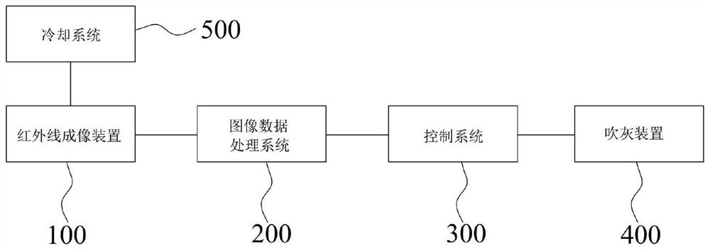
[0031] like figure 1 As shown, this embodiment provides a boiler heating surface soot blowing control system, including an infrared imaging device 100, an image data processing system 200, a control system 300 and a soot blowing device 400, wherein the infrared imaging device 100 can absorb the wavelength and output the thermal imaging of the heating surface, the image data processing system 200 is connected with the infrared imaging device 100, the control system 300 is connected with the image data processing system 200, the image data processing system 200 processes the signal sent by the infrared imaging device 100, and Send the processed temperature data of the heating surface to the control system 300, which is connected to the soot blowing device 400. When the temperature of the heating surface is higher than the first preset temperature, the control system 300 controls the soot blowing device 400 to blow soot.

[0032] The boiler heating surface soot blowing control sy...

Embodiment 2

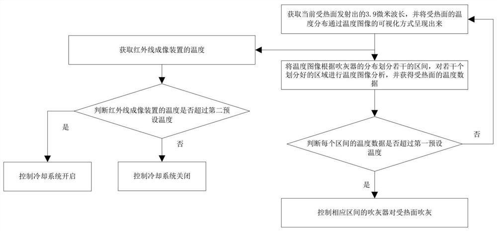
[0041] like figure 2 As shown, this embodiment provides a method for controlling soot blowing on the heating surface of a boiler, comprising the following steps:

[0042] Obtain the 3.9 micron wavelength emitted by the current heating surface, and present the temperature distribution of the heating surface through the visualization of temperature images;

[0043] Divide the temperature image into several intervals according to the distribution of the soot blowers, analyze the temperature image of several divided areas, and obtain the temperature data of the heating surface;

[0044] Determine whether the temperature data in each section exceeds the first preset temperature, if it exceeds the first preset temperature, control the sootblower in the corresponding section to blow soot on the heating surface; if it does not exceed the first preset temperature, repeat the above steps .

[0045] Among them, the infrared imaging device 100 can be used to obtain the wavelength; the ...


PUM


Abstract

The invention belongs to the technical field of boilers, and discloses a soot blowing control system and method for a heating surface of a boiler. The soot blowing control system for the heating surface of the boiler comprises an infrared imaging device, an image data processing system, a control system and a soot blowing device, the infrared imaging device is configured to absorb wavelength emitted by the heating surface and output thermal imaging of the heating surface, and the image data processing system is connected with the infrared imaging device. The control system is connected with the image data processing system, the soot blowing device is connected with the control system, and when the temperature of the heating surface exceeds the first preset temperature, the control system controls the soot blowing device to blow soot. According to the soot blowing control system for the heating surface of the boiler, in the operation process of the boiler, intelligent soot blowing can be conducted on the heating surface, accurate and visual soot blowing of the boiler is achieved, and the soot blowing effect is improved; and waste of high-temperature steam and abrasion and corrosion of the heating surface are effectively reduced, the thinning rate of the heating surface caused by soot blowing is greatly reduced, and the blowing-out risk caused by pipe explosion of the boiler is reduced.

Description

[0001] This application claims the priority of the patent application with application number 202110766271.8 (the application date of the earlier application is July 7, 2021, and the title of the invention is a boiler heating surface soot blowing control system and control method). technical field [0002] The invention relates to the technical field of boilers, in particular to a control system and control method for soot blowing on a heating surface of a boiler. Background technique [0003] Power plant boilers mainly use coal as fuel. During the operation of coal-fired boilers, dust will inevitably appear on the heating surface, and with the development, the quality of coal entering the furnace will also change greatly, seriously deviating from the design coal quality. The problem of contamination on the heating surface will be more serious. The formation of dust will have adverse effects on the safety and economy of the unit. Soot blowing is not only an effective measur...

Claims


Application Information

Patent Timeline
Patent Type & Authority Applications(China)
IPC IPC(8): F23J1/00F23J3/02G05D23/20
CPCF23J1/00F23J3/02G05D23/20
Inventor 刘欣马晓伟张超群李新颖侯伟张宁崔子健林伟杰李驰魏佳付静辛道义
Owner YANTAI LONGYUAN POWER TECH
Why Eureka
Try Eureka