Pantograph catenary arcing measurement sensor calibration device and calibration method

A technology for measuring sensors and calibrating devices, which can be applied to measuring devices, measuring electrical variables, instruments, etc., and can solve problems such as unconsidered effects.

Active Publication Date: 2021-10-26
SOUTHWEST JIAOTONG UNIV +1
View PDF15 Cites 0 Cited by
  • Summary
  • Abstract
  • Description
  • Claims
  • Application Information

AI Technical Summary

Problems solved by technology

However, there are light sources such as incandescent lamps in the tunnel, and the calibration of the

Method used


Image

  • Pantograph catenary arcing measurement sensor calibration device and calibration method
  • Pantograph catenary arcing measurement sensor calibration device and calibration method
  • Pantograph catenary arcing measurement sensor calibration device and calibration method

Examples


Embodiment 1

[0052] As one of the most basic implementations of the present invention, this embodiment discloses a pantograph-catenary arcing measurement sensor calibration device, such as figure 1 and 2 , including a relatively set measurement module and an arcing module, the measurement module includes an adjustment platform 6, and the adjustment platform 6 is provided with a front and rear translation platform 7, and the arc sensor 1 to be calibrated is arranged on the front and rear translation platform 7 Above, the adjustment platform 6 realizes the movement in the up and down and left and right directions under the control command, and the front and rear translation platform 7 drives the arc sensor 1 to be calibrated to realize the movement in the front and rear direction under the control command. When the up and down direction, left and right direction and Combined adjustments in the front and rear directions can ensure that different types of arcing sensors 1 to be calibrated can ...

Embodiment 2

[0056] As a preferred embodiment of the present invention, on the basis of the technical solution of the above-mentioned embodiment 1, further, such as image 3 The arc sensor 1 to be calibrated is set on the forward and backward translation platform 7 through the arc acquisition module. The arc acquisition module is compatible with different types of sensors, which can facilitate the calibration of different types of arc sensors 1 .

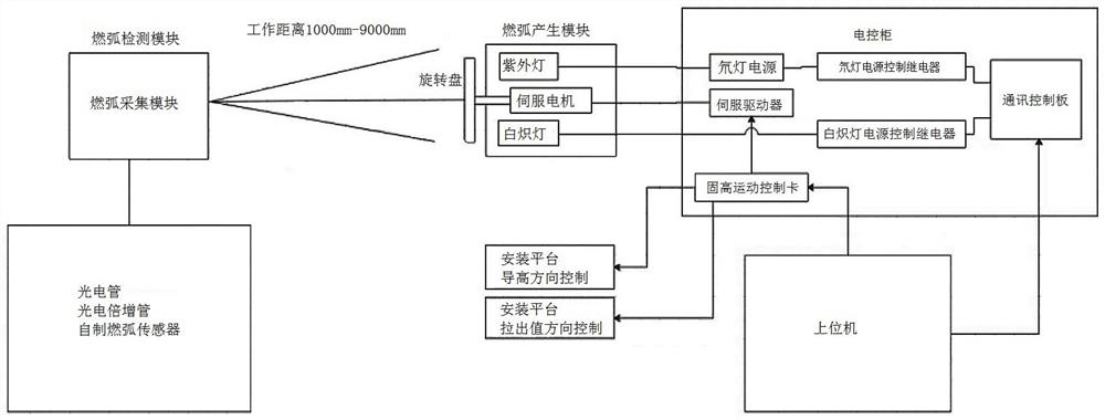
[0057] Preferably, the installation platform 2 moves up and down (height guide direction) and left and right (pull-out value) directions under control instructions. relative movement. Optionally, the arc sensor 1 to be calibrated, the rotating disk 3 for simulating arc generation, the light source, etc. can also be installed and fixed on the measurement module and the arc module respectively.

[0058] More specifically, the vertical movement height range of the installation platform 2 and the adjustment platform 6 is + / -200mm, and the left and ...

Embodiment 3

[0069] Corresponding to the arcing calibration devices of the above-mentioned embodiments 1 and 2, this embodiment provides a calibrating method for the pantograph-catenary arcing measurement sensor, including the steps of installation and adjustment of the arcing sensor 1, data collection and parameter calibration.

[0070] Specifically, the arc sensor installation and adjustment step is to fix the arc sensor 1 to be calibrated on the front and rear translation platform 7 on the adjustment platform 6 in the measurement module, and adjust the adjustment platform 6 and the arc module. The distance between the platforms 2 and the front and rear positions of the front and rear translation platforms 7 adjust the distance between the arc sensor 1 to be calibrated and the rotating disk 3 on the arc module to a predetermined range, and by adjusting the Adjust the height and left and right positions of the platform 6 and / or the installation platform 2, and adjust the guide height in th...


PUM

PropertyMeasurementUnit
Wavelengthaaaaaaaaaa
Diameteraaaaaaaaaa

Abstract

The invention belongs to the technical field of traction power supply system detection and monitoring and discloses a pantograph catenary arcing measurement sensor calibration device. The device comprises a measurement module and an arcing module, simulates actual data such as guide height and pull-out value through an adjusting structure, limits a working distance between a sensor to be calibrated and a light source for simulating arcing, three-way adjustment of the to-be-calibrated pantograph catenary arcing sensor is realized based on an adjustment platform structure, and different light source light transmission frequencies are adjusted through a rotating plate provided with light transmission holes, so pantograph catenary arcing duration, pantograph catenary arcing times and pantograph catenary arcing interval time measured by the pantograph catenary arcing sensor are calibrated in a mode closest to a use environment. The calibration device can calibrate multiple types of arcing sensors at the same time, and the influence of environmental interference light on the arcing sensors is considered at the same time. The invention further discloses a calibration method based on the calibration device for the pantograph catenary arcing measurement sensor.

Description

technical field [0001] The invention belongs to the technical field of detection and monitoring of a traction power supply system, and in particular relates to a calibration device and a calibration method for a pantograph-catenary arcing measurement sensor. Background technique [0002] As an important device for electric traction vehicles to obtain electric energy from the catenary, the pantograph has a close relationship with its contact state with the catenary. [0003] It has become a common practice in the international railway industry to use pantograph-catenary off-line spark and arc detection to evaluate the pantograph-catenary current receiving performance. Before the pantograph-catenary arcing measurement device is installed on the detection train for use, the arcing sensor needs to be calibrated to ensure that it can accurately respond to various characteristics of the pantograph-catenary arcing according to the collected signals. [0004] According to the requi...

Claims


Application Information

Patent Timeline
IPC IPC(8): G01R35/00
CPCG01R35/00
Inventor 占栋向文剑唐磊王宇邓伪兵伍雪松谢宝权郭战江何安春黄越辰唐晓鹏
Owner SOUTHWEST JIAOTONG UNIV
Why Eureka
Try Eureka