A crane rig for lifting large tubular weights

A crane cable and tubular technology, applied in the field of crane rigging, can solve the problems of unfavorable weight center balance and low safety, and achieve the effects of high practicability, labor reduction and safety improvement

Active Publication Date: 2022-05-03
江苏正申索具有限公司
View PDF6 Cites 0 Cited by
  • Summary
  • Abstract
  • Description
  • Claims
  • Application Information

AI Technical Summary

Problems solved by technology

However, when this rigging is used, it not only needs to bind and fix the lifting object, but also is not conducive to the balance of the center of the heavy object, especially for the lifting of large tubular heavy objects, the safety is low, so there is an urgent need for a Crane rigging for lifting large tubular weights

Method used


Image

  • A crane rig for lifting large tubular weights
  • A crane rig for lifting large tubular weights
  • A crane rig for lifting large tubular weights

Examples


Embodiment

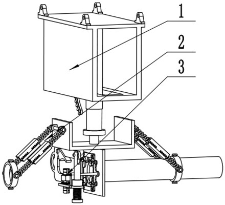
[0024] Example: such as figure 1 , figure 2 , image 3 , Figure 4 , Figure 5 , Figure 6 , Figure 7 The shown crane rigging for lifting large tubular weights includes a steering mechanism 1 , a positioning mechanism 2 , an auxiliary fixing mechanism 3 , and a fixing mechanism 4 .

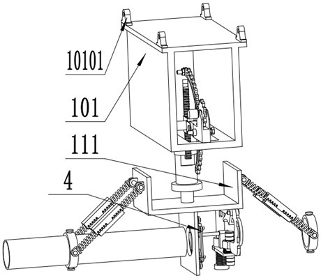
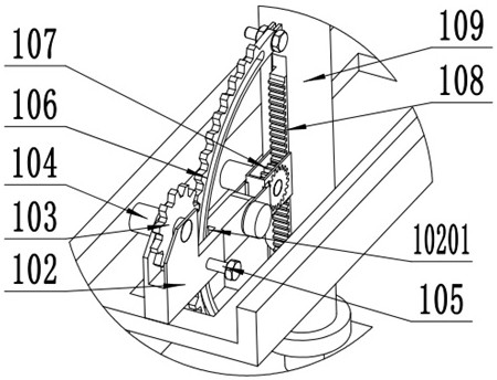
[0025] Such as figure 2 , 3 , the steering mechanism 1 shown in 4, the lifting lug 10101 is fixedly installed on the top of the hanging box 101, the lifting lug 10101 is convenient for the lock to be fixed on various cranes, the support 102 is fixed on the hanging box 101, and the steering gear 103 is rotated and installed On the bearing 102, the steering motor 104 is fixedly installed on the bearing 102, the steering gear 103 is fixedly installed on the output shaft of the steering motor 104, the steering motor 104 drives the steering gear 103 to rotate, and the arc gear 106 is slidably installed On the square hole 10201, the limit pin 105 is fixedly installed on the support 102, the a...


PUM


Abstract

The invention relates to the technical field of crane rigging, in particular to a crane rigging for hoisting large tubular weights, including a steering mechanism, a positioning mechanism, an auxiliary fixing mechanism, and a fixing mechanism; The two ends of the steering mechanism, the auxiliary fixing mechanism and the fixing mechanism are fixedly installed at the bottom of the connecting plate, and the steering mechanism can adjust the installation angle of the tubular weight, which is more practical; the auxiliary gear cooperates with the rack to adjust the installation angle of the tubular weight The installation angle provides auxiliary power, which makes the installation angle more accurate and reduces the labor force; the position adjustment mechanism can adjust the center position of the tubular weight, and can also adjust its own length according to the length of the tubular weight, which provides a safety guarantee for the fixing of the tubular weight; The auxiliary fixing mechanism and the fixing mechanism cooperate with each other to fix the middle of the tubular weight, which improves the safety performance and has high practicability.

Description

technical field [0001] The invention relates to the technical field of crane slings, in particular to a crane sling used for hoisting large tubular weights. Background technique [0002] With the continuous development of industry, the quality of objects that people need to lift in industrial production and construction industries is also increasing. Traditional ropes can no longer fully bear the weight of people hanging objects. Later, people made steel wire ropes by twisting steel wire bundles that meet the requirements of mechanical properties and geometric dimensions according to certain rules. It is first twisted into strands by multi-layer steel wire. Then take the core as the center. It is twisted into a helical shape by a certain number of strands. It consists of steel wire, rope core and grease. After further processing, a convenient-to-use wire rope sling was made. Now it is widely used in steel and chemical industry. Transportation, port and other industries...

Claims


Application Information

Patent Timeline
Patent Type & Authority Patents(China)
IPC IPC(8): B66C1/44B66C13/08
CPCB66C1/445B66C13/085
Inventor 李付林
Owner 江苏正申索具有限公司
Why Eureka
Try Eureka