
Bearing cooling structure of small turbojet engine

A technology of turbojet engine and cooling structure, which is used in engine cooling, engine lubrication, turbine/propulsion cooling, etc., can solve problems such as insufficient fuel combustion, increased engine cost and weight, and sufficient fuel preheating.

Inactive Publication Date: 2021-10-29
浙江华擎航空发动机科技有限公司
View PDF0 Cites 1 Cited by
  • Summary
  • Abstract
  • Description
  • Claims
  • Application Information

AI Technical Summary

Problems solved by technology

[0004] Small turbojet engines operating at high altitudes must face the problem of low fuel temperature. The internal space of small aero-engines is limited, and the heat transfer distance of fuel pipelines in small aero-engines is short, which cannot fully preheat the fuel before combustion, resulting in The te

Method used


Image

  • Bearing cooling structure of small turbojet engine
  • Bearing cooling structure of small turbojet engine
  • Bearing cooling structure of small turbojet engine

Examples


Example Embodiment

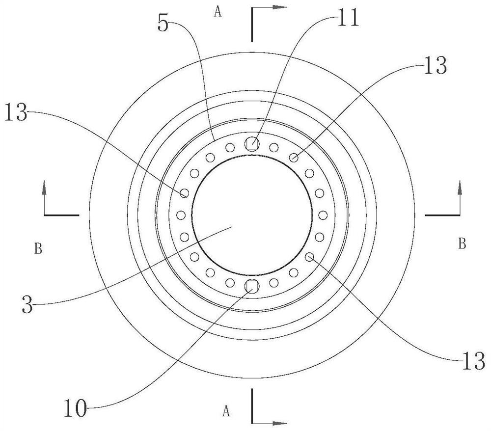
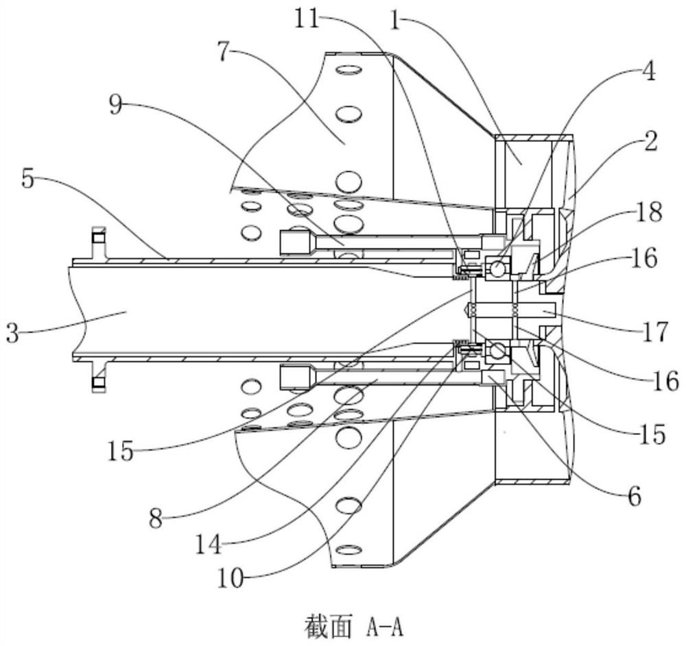
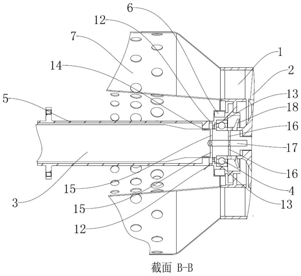
[0015] Example: Figure 1 - Figure 3As shown, a small vortex engine, a bearing cooling structure, a small vortex engine including a turbine stator 1, a turbine rotor 2, a spindle 3, a bearing 4, a bearing support 5, a fuel tube 6, a combustion chamber 7, an oil pipe 8 And the oil pipe 9, the bearing support 5 passes through the combustion chamber 7, and the main shaft 3 passes through the bearing support 5 and is mounted on the bearing support 5 through the bearing 4, and the turbine rotor 2 is mounted on the main shaft 3 and is located at the right of the bearing 4. On the side, the turbine stator 1 is mounted on the bearing support 5, the turbine stator 1 is located on the left side of the turbine rotor 2 and the right side of the bearing 4, and the fuel loop 6 is mounted on the bearing support 5 and located outside the bearing support 5, bearing 4 or all in the inner ring of the fuel loop 6, that is, the fuel loop 6 and the bearing 4, the fuel loop 6, the bearing support 5, the ...


PUM


Abstract

The invention discloses a bearing cooling structure of a small turbojet engine. A first fuel nozzle is arranged on an oil inlet pipe, a second fuel nozzle is arranged on an oil return pipe, a plurality of air guiding holes and a plurality of choke holes are formed in a bearing support, the choke holes are right opposite to a bearing, and a labyrinth sealing structure is arranged between the bearing support and a main shaft. The labyrinth sealing structure is located on the left side of the air guiding holes, the main shaft is provided with a plurality of first flow guiding holes, a plurality of second flow guiding holes and a third flow guiding hole, the first flow guiding holes and the second flow guiding holes extend in the radial direction of the main shaft, the third flow guiding hole extends in the axial direction of the main shaft, and the first flow guiding holes are located in the left side of the bearing. The multiple second flow guiding holes are located in the right side of the bearing, the multiple first flow guiding holes and the multiple second flow guiding holes communicate with the third flow guiding hole, and a flow guiding ring is further fixedly arranged on the main shaft. The bearing cooling structure has the advantages that the bearing can be lubricated and cooled, fuel oil can be preheated, and the combustion chamber efficiency is improved.

Description

technical field [0001] The invention relates to a bearing cooling structure, in particular to a bearing cooling structure of a small turbojet engine. Background technique [0002] At present, small turbojet engines are mainly developed in the direction of high thrust-to-weight ratio, low cost, and simple and reliable structure. The lubricating oil lubrication system for small turbojet engines usually includes lubricating oil tank, lubricating oil pump, oil filter and complex air sealing system, which greatly increases the weight, manufacturing cost and design difficulty of small turbojet engines. Moreover, setting such a complex lubricating oil lubrication system in the relatively limited space of the small turbojet engine will restrict the design of other components. [0003] As we all know, no matter what kind of support method is used for small turbojet engines, due to the influence of heat transfer and radiation of high-temperature components (that is, the turbine struc...

Claims


Application Information

Patent Timeline
IPC IPC(8): F02C7/06F02C7/16F02C7/224
CPCF02C7/06F02C7/16F02C7/224
Inventor 董致臻刘国强黄凯余凯璐吕游谭英杰张文豪
Owner 浙江华擎航空发动机科技有限公司
Learn More