
Pressure gauge movement and working method thereof

A working method and pressure gauge technology, which is applied in the measurement of fluid pressure, fluid pressure measurement through mechanical components, elastic deformation gauge fluid pressure measurement, etc., can solve the movement prone to shaking, pressure gauge measurement error, low efficiency, etc. problems, to achieve high assembly efficiency, avoid damage, and ensure accuracy

Pending Publication Date: 2021-10-29
苏州市维明精工有限责任公司
View PDF0 Cites 0 Cited by
  • Summary
  • Abstract
  • Description
  • Claims
  • Application Information

AI Technical Summary

Problems solved by technology

[0003] However, there are some problems in the existing pressure gauge movement. First, the existing pressure gauge movement needs to be fixed inside the watch case with screws. During the assembly process, the gap between the pressure gauge movement and the watch case Sliding is easy to occur, resulting in low assembly efficiency. Secondly, after the pressure gauge is used for a long time, the fixing screws will rust and the movement will easily shake, resulting in errors in the pressure gauge measurement. In view of this, we propose a pressure gauge movement

Method used


Image

  • Pressure gauge movement and working method thereof
  • Pressure gauge movement and working method thereof
  • Pressure gauge movement and working method thereof

Examples


Embodiment 1

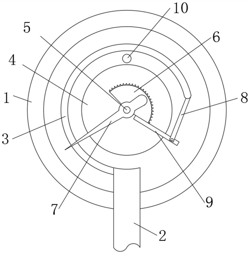
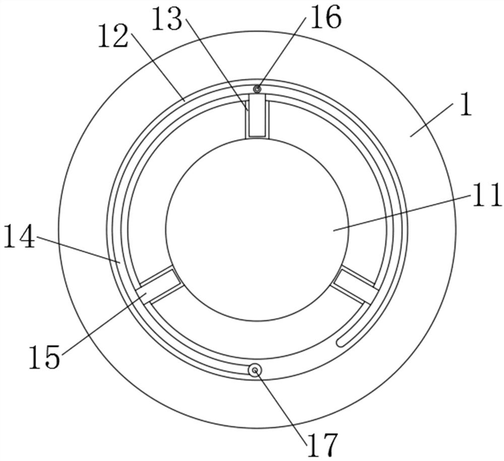
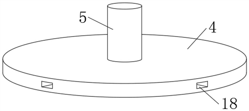
[0027] Such as Figure 1-5 As shown, a pressure gauge movement includes a housing 1, the bottom of the inner wall of the housing 1 is provided with a mounting groove 11, the inside of the mounting groove 11 is provided with a bottom plate 4, and the inside of the housing 1 is provided with a first cavity 12 And the second cavity 13, the first cavity 12 is circular, the second cavity 13 communicates with the first cavity 12 and the installation groove 11, the inside of the first cavity 12 is placed with an air bag 14, the second cavity 13 The inside of the airbag 14 is placed with a board 15, and the side of the airbag 14 near the installation groove 11 is fixedly connected with the board 15. The top of the airbag 14 is fixedly equipped with an inflation valve 16, and the tail of the airbag 14 is fixedly installed with an air supply valve 17. The installation groove 11 has the same shape and size as the bottom plate 4.

[0028] In this embodiment, the side of the bottom plate ...

Embodiment 2

[0034] Such as Figure 1-5 As shown, a pressure gauge movement includes a housing 1, the bottom of the inner wall of the housing 1 is provided with a mounting groove 11, the inside of the mounting groove 11 is provided with a bottom plate 4, and the inside of the housing 1 is provided with a first cavity 12 And the second cavity 13, the first cavity 12 is circular, the second cavity 13 communicates with the first cavity 12 and the installation groove 11, the inside of the first cavity 12 is placed with an air bag 14, the second cavity 13 The inside of the airbag 14 is placed with a board 15, and the side of the airbag 14 near the installation groove 11 is fixedly connected with the board 15. The top of the airbag 14 is fixedly equipped with an inflation valve 16, and the tail of the airbag 14 is fixedly installed with an air supply valve 17. The installation groove 11 has the same shape and size as the bottom plate 4.

[0035] In this embodiment, an intake pipe 2 is installed t...


PUM


Abstract

The invention discloses a pressure gauge movement and a working method thereof. The pressure gauge movement comprises a shell, a mounting groove is formed in the bottom of the inner wall of the shell, a bottom plate is arranged in the mounting groove, a first cavity and a second cavity are formed in the shell, the first cavity is in a circular ring shape, the second cavity is communicated with the first cavity and the mounting groove, an air bag is placed in the first cavity, an inserting plate is placed in the second cavity, and the side, close to the mounting groove, of the air bag is fixedly connected with the inserting plate. According to the pressure gauge movement, the pressure gauge movement can be rapidly assembled through the mounting groove, the air bag, the inserting plate and the inserting hole, the bottom plate is placed in the mounting groove to limit the movement and prevent the movement from sliding, then an inflator is used, an air outlet pipe of the inflator and an inflation valve are fixed, air is inflated into the air bag, the air bag is inflated and expands to extrude the inserting plate out of the second cavity, so that the inserting plate is inserted into the inserting hole, and the bottom plate is fixed.

Description

technical field [0001] The present application relates to the technical field of pressure gauge movement, in particular to a pressure gauge movement and its working method. Background technique [0002] A pressure gauge refers to an instrument that uses elastic elements as sensitive elements to measure and indicate pressure higher than the environment. It is widely used. It pervades almost all industrial processes and scientific research fields. The elastic sensitive element of the pressure gauge has the characteristics of high mechanical strength and convenient production, which makes the mechanical pressure gauge more and more widely used. The working principle of the pressure gauge is through the elastic deformation of the sensitive element in the gauge, such as Bourdon Tube, diaphragm box and bellows, etc., and then the conversion mechanism of the watch movement transmits the pressure deformation to the pointer, causing the pointer to rotate to display the pressure. [...

Claims


Application Information

Patent Timeline
Patent Type & Authority Applications(China)
IPC IPC(8): G01L7/04G01L19/00G01L19/14
CPCG01L7/041G01L19/00G01L19/14
Inventor 戈彬戈维敏
Owner 苏州市维明精工有限责任公司
Learn More