Fault monitoring method for resonant device and laser radar

A technology of fault monitoring and laser radar, which is applied in the testing of machines/structural components, optical instrument testing, instruments, etc., can solve problems such as difficult to ensure devices, and achieve the effect of avoiding economic losses or safety accidents

Pending Publication Date: 2021-10-29
HESAI TECH CO LTD
View PDF0 Cites 2 Cited by
  • Summary
  • Abstract
  • Description
  • Claims
  • Application Information

AI Technical Summary

Problems solved by technology

But in practice, it is still difficult to ensure that 100% of the devices will not fail within the expected working life
[0006] Fatigue failure of devices is therefore a very complex problem, and abnormal failures may still be unavoidable, which is not helpful even with large-scale life experiments

Method used


Image

  • Fault monitoring method for resonant device and laser radar
  • Fault monitoring method for resonant device and laser radar
  • Fault monitoring method for resonant device and laser radar

Examples


Embodiment Construction

[0045] Hereinafter, some exemplary embodiments are simply described. As will be appreciated by those skilled in the art, the described embodiments can be modified in a variety of different ways without departing from the spirit or scope of the invention. Thus, the drawings and descriptions are considered to be exemplary rather than restrictive.

[0046] In the description of the present invention, it is necessary to understand that the term * # * center * # *, * # * portrait * # *, * # * horizontal * # *, * # * length * # *, * # * width * # *, * # * Thickness * # *, * # * on * # *, * # * *, * # * after * # *, * # * left * # * , * # * * # *, * # * Horizontal * # *, * # * top * # *, * # * bottom * # *, * # * within * # *, * # * Outside * # *, * # * Clock-clock * # *, * # * The orientation or positional relationship of the indication of the indication * # * is based on the orientation or positional relationship shown in the drawing, just for easy description Invention and simplificatio...


PUM


Abstract

The invention discloses a fault monitoring method for a resonant device. The fault monitoring method comprises the following steps: detecting a measured value of a characteristic parameter of the resonant device; obtaining a preset normal range corresponding to the characteristic parameter; and according to the preset normal range and the measurement value, judging whether the resonant device works normally or not. The invention also discloses a laser radar, which comprises a galvanometer and a fault detection unit for the galvanometer. The invention provides a method for early warning the failure of the device based on the monitoring of the dynamic characteristics of the device, so that the parts can be replaced in advance, and economic loss or safety accidents are avoided.

Description

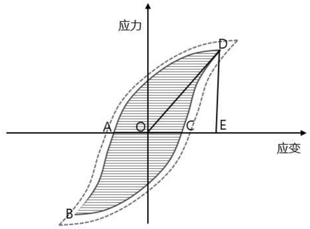
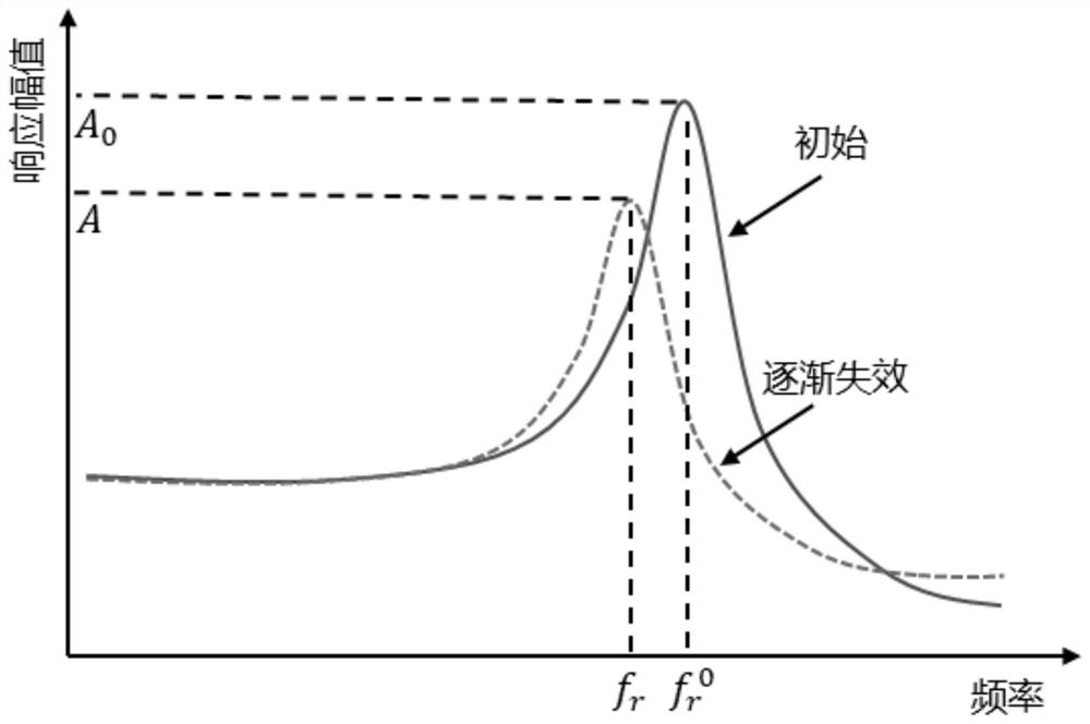
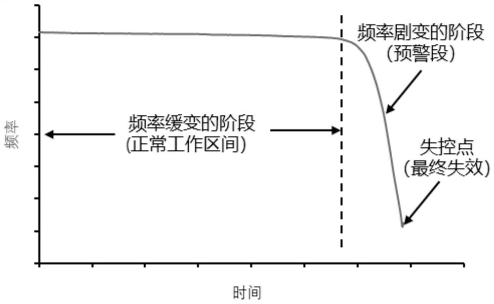
Technical field [0001] The present disclosure relates to the field of fault detection, and more particularly to a fault monitoring method that can be used in a resonant device and a laser radar including a sprayer and a fault detection unit. Background technique [0002] Mechanical resonance devices such as various types of scanning gauges, resonant gyroscopes, etc., often work in their own resonance points to achieve maximum amplitude and output; in such devices, there is generally high-frequency constant mechanical structure, and materials are subjected to circulation loads. The fatigue characteristics will be demonstrated, the higher the external load, the less the number of cycles required when arriving at the expiration. On the other hand, the actual number of devices works throughout the life cycle is often very high, such as 10 ^ 10 magnitude, although the life of the device high-cycle work can be made by a certain low period life experiment and the corresponding statistic...

Claims


Application Information

Patent Timeline
Patent Type & Authority Applications(China)
IPC IPC(8): G01S7/497G01S7/481G01S17/02G01M11/00
CPCG01S7/497G01S7/481G01S17/02G01M11/00
Inventor 毛胜平向少卿
Owner HESAI TECH CO LTD
Why Eureka
Try Eureka