Method for detecting fuse through microcomputer, photovoltaic power grid, UPS power source special for computer and artificial intelligent robot

A technology of microcomputers and fuses, applied in the direction of measuring electricity, measuring electrical variables, instruments, etc., can solve the problems of real-time detection of circuit failure, damage to the longitudinal capacity of the battery pack, and difficult circuits.

Inactive Publication Date: 2016-05-04
范甬挺
View PDF7 Cites 2 Cited by
  • Summary
  • Abstract
  • Description
  • Claims
  • Application Information

AI Technical Summary

Problems solved by technology

[0002] Instant self-test during circuit operation is of great significance to prevent circuit safety problems. The existing technology does not have an instant test method for diodes whose negative pole is connected to the high voltage pole of the power supply, that is to say, when the positive pole of a diode is connected to the high voltage pole of the power supply If the diode is suddenly open circuit (due to breakdown, burning, etc.), then the circuit is difficult to detect immediately by the self-test circuit or program, which is a huge trouble for instant detection circuit failure;
[0003] Adding a fuse to a single battery in the storage module of the power supply can prevent the battery from being damaged due to excessive current. However, after the fuse breaks, the battery cannot continue to charge and discharge, which damages the vertical capacity of the battery pack. The pick-up, maintenance and replacement of the battery in the battery pack is carried out during the overall maintenance of the battery pack, and the middle section of the battery pack as a whole needs to be carried out, which is unfavorable for systems that require continuous operation of buffered electric energy

Method used


Image

  • Method for detecting fuse through microcomputer, photovoltaic power grid, UPS power source special for computer and artificial intelligent robot

Examples


Embodiment 1

[0058] Implementation example 1, the method that uses microcomputer to detect fuse in real time, is characterized in that:

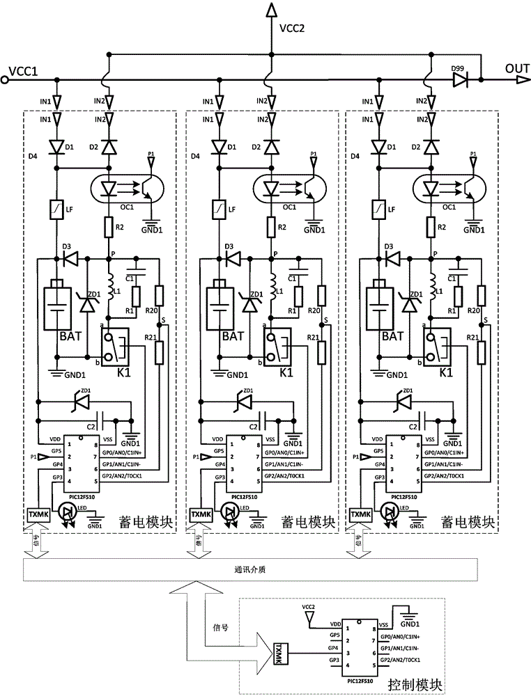
[0059] based on figure 1 In the power storage module shown, the power storage module includes an input node IN1, an output node IN2, a fuse LF, a second resistor R2, a first resistor R1, a first capacitor C1, a first inductor L1, a first diode D1, a first Second capacitor C2, second diode D2, third diode D3, No. 0 sampling resistor R20, No. 1 sampling resistor R21, switch K1, rechargeable battery BAT, power supply location GND1, microcontroller PIC12F510, bootstrap node P, Sampling node S, optocoupler OC1;

[0060] In the power storage module: the anode of the first diode D1 is connected to the input node IN1, and the cathode of the first diode D1 is connected to the anode of the rechargeable battery BAT via a fuse;

[0061] In the power storage module: the cathode of the second diode D2 is connected to the output node IN2, and the anode of the second ...

Embodiment 2

[0100] Implementation example 2, such as figure 1 As shown, the micro-power battery pack is characterized in that it includes a plurality of power storage modules, a control module, an isolation diode D99, a second power point VCC2, a power input point VCC1, and a power output point OUT;

[0101] The input nodes IN1 of all power storage modules are connected to the power supply input point VCC1;

[0102] The output nodes IN2 of all the power storage modules are connected to the second power supply point VCC2;

[0103] The power input point VCC1 is connected to the anode of the isolation diode D99, and the power output point OUT is connected to the cathode of the isolation diode D99;

[0104] The second power supply point VCC2 is connected to the cathode of the isolation diode D99;

[0105] The control module can communicate with each power storage module, and the control module can instruct each power storage module to perform a self-check operation to detect the state of th...

Embodiment 3

[0107] Implementation example 3, a dedicated UPS power supply for computers, has an electrical storage device, and has the technical scheme of the implementation example 1 with the electrical storage device.


PUM


Abstract

A method for detecting a fuse in real time through a microcomputer is characterized in that the method is based on an electric power storage module which comprises an input node, an output node, the fuse (LF), a second resistor (R2), a first resistor (R1), a first capacitor, a first inductor (L1), a first diode, a second capacitor (C2), a second diode (D2), a third diode, a number zero sampling resistor, a first sampling resistor, a switch, a rechargeable battery, a power source site, a single-chip microcomputer, a bootstrapping node, a sampling node and an optocoupler. A photovoltaic power grid, a UPS power source special for a computer and an intelligent robot are provided with the electric power storage device of the technical scheme. The method is low in cost, application is flexible, the service life is long, the fuse is not prone to damage, stable and reliable, whether an open circuit happens to a diode with the positive electrode connected with a high-voltage electrode of a direct-current power source or not is tested through the electric energy of the direct-current power source under the situation that the direct-current power source runs, and the open circuit of the fuse can be reliably detected in real time by means of a bypass.

Description

technical field [0001] The invention belongs to the field of applied electronics, and in particular relates to a method for real-time detection of a fuse using a microcomputer. Background technique [0002] Instant self-test during circuit operation is of great significance to prevent circuit safety problems. There is no instant test method for diodes whose negative pole is connected to the high voltage pole of the power supply in the prior art, that is to say, when the positive pole of a diode is connected to the high voltage pole of the power supply In the case that the diode suddenly opens (due to breakdown, burning, etc.), then the circuit is difficult to detect immediately by the self-test circuit or program, which is a huge trouble for instant detection circuit failure; [0003] Adding a fuse to a single battery in the storage module of the power supply can prevent the battery from being damaged due to excessive current. However, after the fuse breaks, the battery cann...

Claims


Application Information

Patent Timeline
Patent Type & Authority Applications(China)
IPC IPC(8): G01R31/02
CPCG01R31/58
Inventor 刘伟聂黎生聂新明赵新生薛家祥文元美田亚平
Owner 范甬挺
Why Eureka
Try Eureka