Supercharge Your Innovation With Domain-Expert AI Agents!

Optical fiber image correction method and device and computer readable storage medium

An image correction and optical fiber technology, applied in the field of image processing, can solve problems affecting image quality, pixel differences, etc., and achieve the effect of improving accuracy, ensuring consistency, and realizing optical fiber drift correction

Pending Publication Date: 2021-10-29
SUZHOU MICROVIEW MEDICAL TECH CO LTD
View PDF0 Cites 1 Cited by
  • Summary
  • Abstract
  • Description
  • Claims
  • Application Information

AI Technical Summary

Problems solved by technology

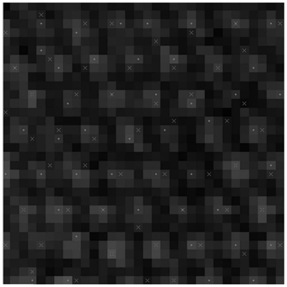
Ideally, the centers of the optical fiber units in the same optical fiber are completely coincident at each moment in the same use process. However, if figure 1 As shown in , due to the fiber drift phenomenon, there is a certain pixel difference in the center position between the two moments
In the process of image reconstruction, it is necessary to determine the position of the center of each fiber unit to implement a fast degriding method, and the existence of fiber drift will make fiber information in the wrong position be extracted during fiber image processing, which greatly affects Image Quality
And the deviation of the gray value of the center of each fiber unit from each other will also significantly affect the image quality

Method used


Image

  • Optical fiber image correction method and device and computer readable storage medium
  • Optical fiber image correction method and device and computer readable storage medium
  • Optical fiber image correction method and device and computer readable storage medium

Examples


Embodiment Construction

[0049] In order to enable those skilled in the art to better understand the technical solutions of the present disclosure, the present disclosure will be described in detail below in conjunction with the accompanying drawings and specific embodiments. Embodiments of the present disclosure will be described in further detail below in conjunction with the accompanying drawings and specific embodiments, but are not intended to limit the present disclosure.

[0050] "First", "second" and similar words used in the present disclosure do not indicate any order, quantity or importance, but are only used to distinguish different parts. Words like "comprising" or "comprising" mean that the elements preceding the word cover the elements listed after the word, and do not exclude the possibility of also covering other elements. "Up", "Down", "Left", "Right" and so on are only used to indicate the relative positional relationship. When the absolute position of the described object changes, ...


PUM


Abstract

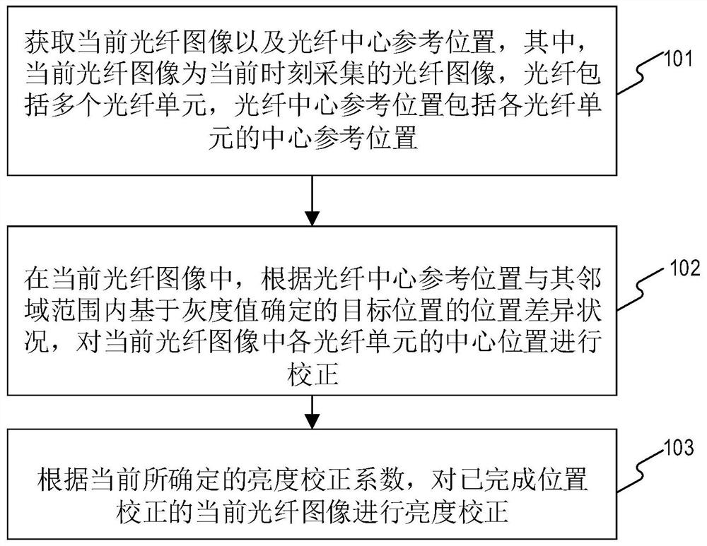
The invention relates to an optical fiber image correction method and device and a computer readable storage medium. The method comprises the steps of obtaining a current optical fiber image and an optical fiber center reference position; in the current optical fiber image, correcting the central position of each optical fiber unit in the current optical fiber image according to a position difference condition between the optical fiber central reference position and a target position determined based on a gray value in a neighborhood range of the optical fiber central reference position; and according to the currently determined brightness correction coefficient, performing brightness correction on the current optical fiber image of which the position correction is completed. Therefore, in the process of observing an object by using the microendoscope, not only can the optical fiber drift correction be quickly and efficiently realized on the acquired optical fiber image, but also the real-time parameter correction can be quickly and efficiently realized, so that the optical fiber image quality in the observation process is improved, the consistency of the optical fiber image quality is ensured, and the accuracy of subsequent diagnosis is improved.

Description

technical field [0001] The present disclosure relates to the field of image processing, and in particular, relates to an optical fiber image correction method, device, and computer-readable storage medium. Background technique [0002] Microendoscopes are widely used in medical observation and detection. Optical fibers and vibrating mirrors are important components of microendoscopes. A whole optical fiber is usually composed of tens of thousands of optical fiber units. Usually, each The center position of each fiber unit is fixed. In actual use, due to the limitation of the scanning accuracy of the galvanometer and the bending change of the optical fiber during use, it is impossible to ensure that each scan is at the exact same position when the end face is fixed. Therefore, as time changes, the scanning position of the galvanometer and the position of the fiber will change, and correspondingly, the center position of each fiber unit in a whole fiber will also change. Thi...

Claims


Application Information

Patent Timeline
IPC IPC(8): G06T5/00G06T7/66G06T7/90G06T17/20
CPCG06T7/90G06T7/66G06T17/20G06T5/80G06T5/50G06T5/92G06T5/94G06T2207/20224
Inventor 何琼邵金华孙锦白迪
Owner SUZHOU MICROVIEW MEDICAL TECH CO LTD
Features
  • R&D
  • Intellectual Property
  • Life Sciences
  • Materials
  • Tech Scout
  • Unparalleled Data Quality
  • Higher Quality Content
  • 60% Fewer Hallucinations
Learn More