Insulating fireproof cable trough box

A fire-resistant cable and slot box technology, used in electrical components, springs/shock absorbers, vibration suppression adjustment, etc., can solve the problems of cable winding, poor shock resistance, cable danger, etc., to improve installation efficiency, improve safety, and safety. high sex effect

Inactive Publication Date: 2021-10-29
镇江腾宇电能设备有限公司
View PDF8 Cites 0 Cited by
  • Summary
  • Abstract
  • Description
  • Claims
  • Application Information

AI Technical Summary

Problems solved by technology

[0003] Existing cable trough boxes are usually installed horizontally or vertically when in use, and usually require specific fixing parts during installation, which is inconvenient during installation, has poor shock resistance, and is not stable enough. Secondly, the existing cable trough boxes are in use It is impossible to isolate the cables according to the number of cables, and the cables are prone to entanglement during use, and there will be a certain danger when the cables have a short-circuit leakage. The cover plate of the box usually needs to be fixed by screws, which is not easy to disassemble. Therefore, we propose an insulated fire-resistant cable trough box

Method used


Image

  • Insulating fireproof cable trough box
  • Insulating fireproof cable trough box
  • Insulating fireproof cable trough box

Examples


Embodiment 1

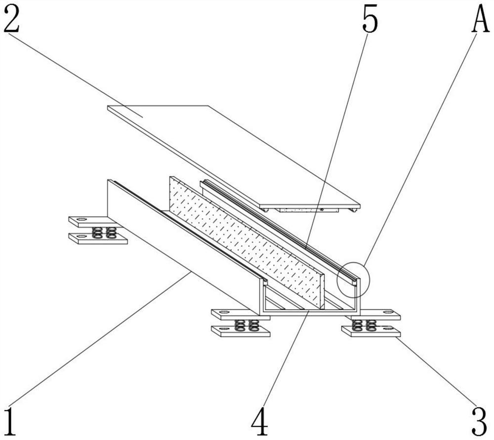
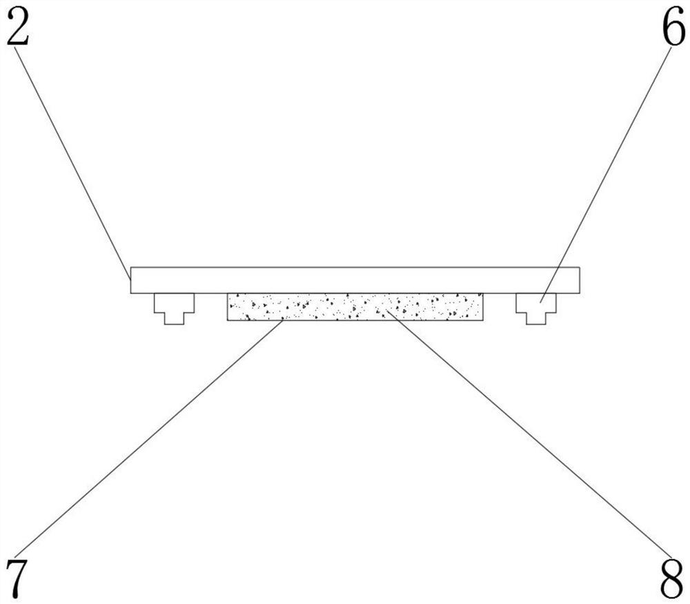
[0022] Such as Figure 1-2 As shown, an insulating fire-resistant cable trough box includes a bottom box 1 and an upper box cover 2, the bottom box 1 is located below the upper box cover 2, and the outer surface of the lower end of the bottom box 1 is provided with a fixing mechanism 3, and the bottom box The middle part of the box 1 is provided with a protective mechanism 4, the inner surface of both sides of the bottom box box 1 is provided with a concave magnetic strip 5, and the outer surface of the lower end of the upper box cover 2 is provided with a convex iron strip 6 and a fireproof airbag bag 7. Iron bar 6 is positioned at the both sides of fireproof airbag bag 7, and the interior of fireproof airbag bag 7 is provided with carbon dioxide 8.

Embodiment 2

[0024] On the basis of Embodiment 1, such as image 3 As shown, the fixing mechanism 3 includes an upper fixing piece 301, a spring 302, a lower fixing piece 303, a No. 1 screw hole 304 and a No. 2 screw hole 305, the spring 302 is located on the lower end outer surface of the upper fixing piece 301, and the lower fixing piece 303 is located On the outer surface of one end of 302, the No. 1 screw hole 304 is located in the middle of the upper fixing piece 301, the second screw hole 305 is located in the middle of the lower fixing piece 303, and the outer surface of the lower end of the upper fixing piece 301 is welded to the other end outer surface of the spring 302. , the outer surface of one end of the spring 302 is welded to the upper outer surface of the lower fixing piece 303, the number of springs 302 is two groups, the size of the first screw hole 304 is the same as the size of the second screw hole 305, and the first screw hole 304 It is opposite to the No. 2 screw hol...

Embodiment 3

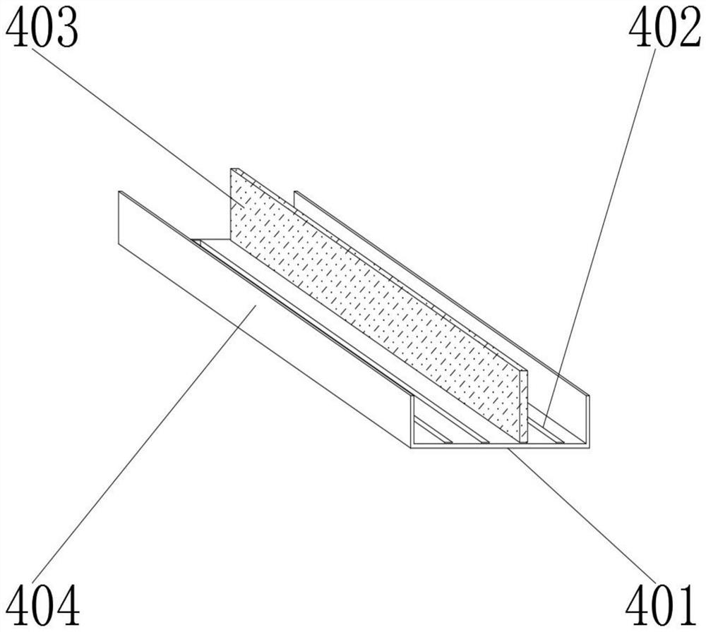
[0026] On the basis of Embodiment 1, such as Figure 4 As shown, the protective mechanism 4 includes a bottom plate 401, a connecting groove 402, a partition plate 403 and a side plate 404, the connecting groove 402 is located in the middle of the bottom plate 401, the partition plate 403 is located in the middle of the connecting groove 402, and the side plate 404 is located in the bottom plate The outer surface of the upper end of 401, the bottom plate 401 and the side plate 404 are integrally formed, the connecting groove 402 is opened in the middle of the bottom plate 401, the number of connecting grooves 402 is four groups, and the partition plate 403 is detachable from the bottom plate 401 through the connecting groove 402 connection, the separating plate 403 is made of glass fiber, the bottom plate 401 and the side plate 404 are made of insulating rubber, and the protective mechanism 4 can separate different types of cables through the separating plate 403 during use. T...


PUM


Abstract

The invention discloses an insulating fire-resistant cable trough box, and relates to the field of cable trough boxes. The insulating fire-resistant cable trough box comprises a bottom box and an upper box cover, the bottom box is located below the upper box cover, and a fixing mechanism is arranged on the outer surface of the lower end of the bottom box. According to the insulating fire-resistant cable trough box, through arrangement of a protection mechanism, when the insulating fire-resistant cable trough box is used, the use safety of cables can be improved, the cables can be prevented from being wound, different types of cables can be distinguished, the insulating fire-resistant effect can be achieved; and through arrangement of the fixing mechanism, the mounting efficiency of the cable trough box can be improved when the insulating fire-resistant cable trough box is used;, different installation modes are convenient to carry out, the box is stable during use; the upper box cover and the bottom box are convenient to disassemble and assemble through concave magnetic strips and convex iron strips, and the box is convenient and fast to use; a certain fire extinguishing effect can be achieved through carbon dioxide in the fireproof air bag when the fireproof air bag is used, and the safety is high during use; and the use effect is better than that of a traditional mode.

Description

technical field [0001] The invention relates to the field of cable trough boxes, in particular to an insulating and fire-resistant cable trough box. Background technique [0002] The cable trough box (collection trough) is a long trough with a flat cross section, with or without a cover plate, which is installed on the bracket after connection, which is equivalent to an overhead cable trench. The trunking also has the function of electromagnetic shielding to prevent the expansion of cable accidents. [0003] Existing cable trough boxes are usually installed horizontally or vertically when in use, and usually require specific fixing parts during installation, which is inconvenient during installation, has poor shock resistance, and is not stable enough. Secondly, the existing cable trough boxes are in use It is impossible to isolate the cables according to the number of cables, and the cables are prone to entanglement during use, and there will be a certain danger when the c...

Claims


Application Information

Patent Timeline
Patent Type & Authority Applications(China)
IPC IPC(8): H02G3/04F16F15/067
CPCH02G3/0487H02G3/0412F16F15/067
Inventor 王红军
Owner 镇江腾宇电能设备有限公司
Why Eureka
Try Eureka