Soil-rock geological foundation pit forming construction method

A construction method, the technology of soil intercalation, applied in the direction of basic structure engineering, excavation, construction, etc., can solve the problems of inefficiency, slow progress, low efficiency, etc., and achieve the effects of ensuring disturbance, speeding up construction progress, and ensuring the quality of foundation pits

Pending Publication Date: 2021-11-02
CCCC TUNNEL ENG +1
View PDF6 Cites 0 Cited by
  • Summary
  • Abstract
  • Description
  • Claims
  • Application Information

AI Technical Summary

Problems solved by technology

[0002] The foundation pit is an essential part of the process of infrastructure construction. However, there are various construction methods for foundation pit excavation. It is a small foundation pit, the national standard protective fence foundation pit length * width * height = 60*60*70cm is relatively small, manual excavation is affected by the soil and rocks, and the construction cannot be carried out every time the shovel touches the stones, the progress is slow and inefficient , the span of the 12-36° column of the protective fence is generally 1.15m. If the excavator digs a large foundation pit, the foundation pit and the foundation pit are connected to each other to form a ditch. However, after the installation of the protective fence column and the lower sill is completed, Then backfill, it is difficult and inefficient to backfill the foundation pit due to the impact of the lower sill

Method used


Image

  • Soil-rock geological foundation pit forming construction method
  • Soil-rock geological foundation pit forming construction method
  • Soil-rock geological foundation pit forming construction method

Examples


Embodiment Construction

[0022] In order to make the purpose, technical solutions and advantages of the embodiments of the present invention clearer, the technical solutions in the embodiments of the present invention will be clearly and completely described below in conjunction with the drawings in the embodiments of the present invention. Obviously, the described embodiments It is a part of embodiments of the present invention, but not all embodiments. Based on the embodiments of the present invention, all other embodiments obtained by persons of ordinary skill in the art without creative efforts fall within the protection scope of the present invention.

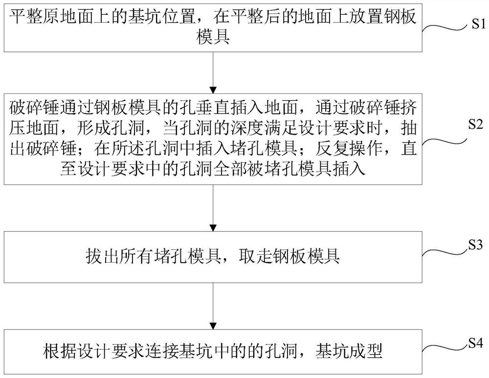
[0023] like figure 1 As shown, the present invention includes:

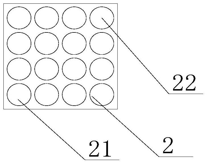
[0024] S1. Level the position of the foundation pit on the original ground, and place the steel plate mold 2 on the leveled ground;

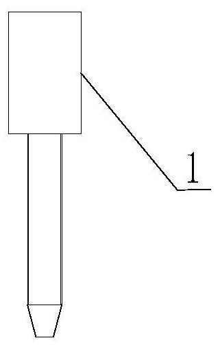
[0025] Specifically, the original ground is flat. According to the position of the measuring line, use the breaker 1 to level the original ground. T...


PUM


Abstract

The invention discloses a soil-rock geological foundation pit forming construction method. The method comprises the steps that S1, the position of a foundation pit on the original ground is slightly leveled, and a steel plate mold is placed on the ground; S2, a breaking hammer is vertically inserted into the ground through an opening of the steel plate mold, holes are dug through the breaking hammer till the depth of the holes meets the design requirement, and the breaking hammer is pulled out; S3, hole plugging molds are inserted into the pit holes dug by the breaking hammer; S4, the breaking hammer is vertically inserted and pulled out according to the number, the hole plugging mold is inserted, and the operation is repeated until the hole plugging mold is inserted into the last hole; S5, all the hole plugging molds are pulled out, and the steel plate mold is taken away; and S6, the holes in the foundation pit are connected, and a protective fence stand column foundation pit is formed. The construction progress is accelerated: compared with traditional foundation pit excavation, the method has the advantages that extrusion hole forming of existing equipment, namely the breaking hammer is rapid and does not waste resources. And meanwhile, the construction quality is guaranteed: the foundation pit quality is guaranteed, surrounding rock and soil cannot be disturbed, and the disturbance of the bottom of the foundation pit is guaranteed.

Description

technical field [0001] The invention relates to the field of engineering construction, in particular to a construction method for forming a soil-interbedded rock geological foundation pit. Background technique [0002] The foundation pit is an essential part of the process of infrastructure construction. However, there are various construction methods for foundation pit excavation. It is a small foundation pit, the national standard protective fence foundation pit length * width * height = 60*60*70cm is relatively small, manual excavation is affected by the soil and rocks, and the construction cannot be carried out every time the shovel touches the stones, the progress is slow and inefficient , the span of the 12-36° column of the protective fence is generally 1.15m. If the excavator digs a large foundation pit, the foundation pit and the foundation pit are connected to each other to form a ditch. However, after the installation of the protective fence column and the lower s...

Claims


Application Information

Patent Timeline
Patent Type & Authority Applications(China)
IPC IPC(8): E02D17/02
CPCE02D17/02E02D2250/0007E02D2300/0029
Inventor 武海军张振兴张恩惠王冠淇沈峰郇恒德张泽林李万麟王冬冬赵明张景峰王藉彬赵山水孙海鑫
Owner CCCC TUNNEL ENG
Why Eureka
Try Eureka