Small excavator jammer
A technology of jammers and excavators, applied in the field of jammers, can solve the problems of time-consuming and labor-intensive disassembly, and achieve the effect of increasing friction
- Summary
- Abstract
- Description
- Claims
- Application Information
AI Technical Summary
Problems solved by technology
Method used
Image
Examples
Embodiment 1
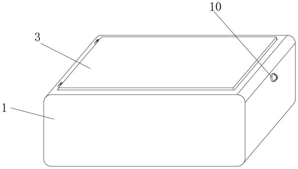
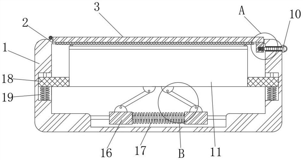
[0025] Embodiment one, by Figure 1-4 Given, a small excavator jammer includes a jammer housing 1, a disassembly mechanism and a shock absorbing mechanism. The interior of the jammer housing 1 is provided with a mounting cavity, and the top of the jammer housing 1 is provided with a fixed opening 2. 1 is slidingly connected with a jammer device main body 11;
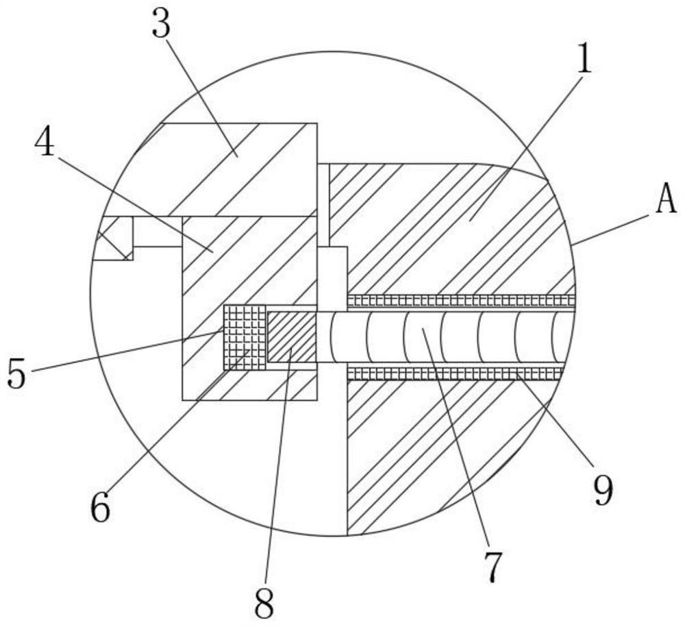
[0026] The disassembly mechanism includes a blocking plate 3, a clamping block 4, a limit groove 5, a permanent magnet block A6, a pull rod 7 and a permanent magnet block B8, the blocking plate 3 is rotatably connected in the fixed port 2, and the clamping block 4 is fixedly connected in the On one side of the bottom of the blocking plate 3, the clamping block 4 is slidably connected in the fixed port 2, the limiting groove 5 is set on one side of the clamping block 4, the permanent magnet block A6 is fixedly connected in the limiting groove 5, and the jammer One side of the housing 1 is provided with a fixing hole, the...
Embodiment 2
[0027]Embodiment 2, on the basis of Embodiment 1, the damping mechanism includes a guide rod 15, a buffer spring 17, two mounting seats 12, two rotating parts 13, two fixing seats 14 and two sliders 16, two The mounting base 12 is symmetrically and fixedly connected to the bottom of the main body 11 of the jammer device, the two rotating parts 13 are respectively rotationally connected in the two mounting bases 12, and the two fixing bases 14 are respectively rotatably socketed on the two rotating parts 13 away from the mounting base 12 On one side, the guide rod 15 is fixedly connected in the jammer housing 1, and the two sliders 16 are symmetrically slid and sleeved on the guide rod 15, the top of the slider 16 is fixedly connected with the bottom of the fixed seat 14, and the buffer spring 17 is sleeved On the guide rod 15, the two ends of the buffer spring 17 are respectively fixedly connected to the opposite sides of the two sliders 16. When the cab of the excavator vibrat...
Embodiment 3
[0028] Embodiment 3, on the basis of Embodiment 1, the end of the pull rod 7 away from the permanent magnet block B8 is fixedly connected with a pull plate 10, and the other side of the pull plate 10 is fixedly connected with a pull ring. By setting the pull plate 10 and the pull ring, It can better apply force when the personnel pulls the pull rod 7.
PUM
 Abstract
Description
Claims
Application Information
 - R&D
- Intellectual Property
- Life Sciences
- Materials
- Tech Scout
- Unparalleled Data Quality
- Higher Quality Content
- 60% Fewer Hallucinations
Browse by: Latest US Patents, China's latest patents, Technical Efficacy Thesaurus, Application Domain, Technology Topic, Popular Technical Reports.
© 2025 PatSnap. All rights reserved.Legal|Privacy policy|Modern Slavery Act Transparency Statement|Sitemap|About US| Contact US: help@patsnap.com


