Swing arm floor tile laying device

A laying device and a technology for floor tiles, which are applied in the direction of construction and building construction, can solve the problems of inability to adjust the width of the gap between floor tiles and floor tiles, easy deviation, and errors, so as to improve the efficiency of laying bricks and the time for absorbing bricks Short, the effect of reducing the chance of danger

Inactive Publication Date: 2021-11-02
中一北工科技发展股份有限公司
View PDF6 Cites 2 Cited by
  • Summary
  • Abstract
  • Description
  • Claims
  • Application Information

AI Technical Summary

Problems solved by technology

[0002] Floor tile laying is an indispensable part of decoration. At present, floor tile laying is mostly done manually. This method of laying is inefficient. Therefore, brick laying vehicles have appeared on the market to replace manual laying of floor tiles, thereby improving efficiency.
[0003] However, when using a tile-laying vehicle to lay floor tiles, errors will inevitably occur. At present, there is no tile-laying vehicle that can solve the adjustment error of the tile-laying vehicle when laying floor tiles, and when laying floor tiles, the gap between the floor tiles The gap does not have only one width, and the existing tile laying vehicle cannot adjust the gap width between the floor tiles during the laying process
[0004] When using a brick-laying truck for laying, it is also necessary to transport bricks with the brick-laying truck to cooperate with the brick-laying truck. However, when the brick-laying truck is docked with the brick-laying truck, it is easy to shift

Method used


Image

  • Swing arm floor tile laying device
  • Swing arm floor tile laying device
  • Swing arm floor tile laying device

Examples


Embodiment Construction

[0025] In order to make the purpose, technical solutions and advantages of the embodiments of the present invention clearer, the technical solutions in the embodiments of the present invention will be clearly and completely described below in conjunction with the drawings in the embodiments of the present invention. Obviously, the described embodiments It is a part of embodiments of the present invention, but not all embodiments. The components of the embodiments of the invention generally described and illustrated in the figures herein may be arranged and designed in a variety of different configurations. Accordingly, the following detailed description of the embodiments of the invention provided in the accompanying drawings is not intended to limit the scope of the claimed invention, but merely represents selected embodiments of the invention. Based on the embodiments of the present invention, all other embodiments obtained by persons of ordinary skill in the art without cre...


PUM


Abstract

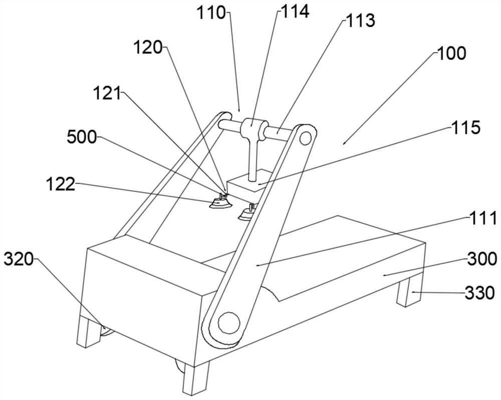
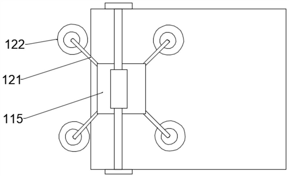
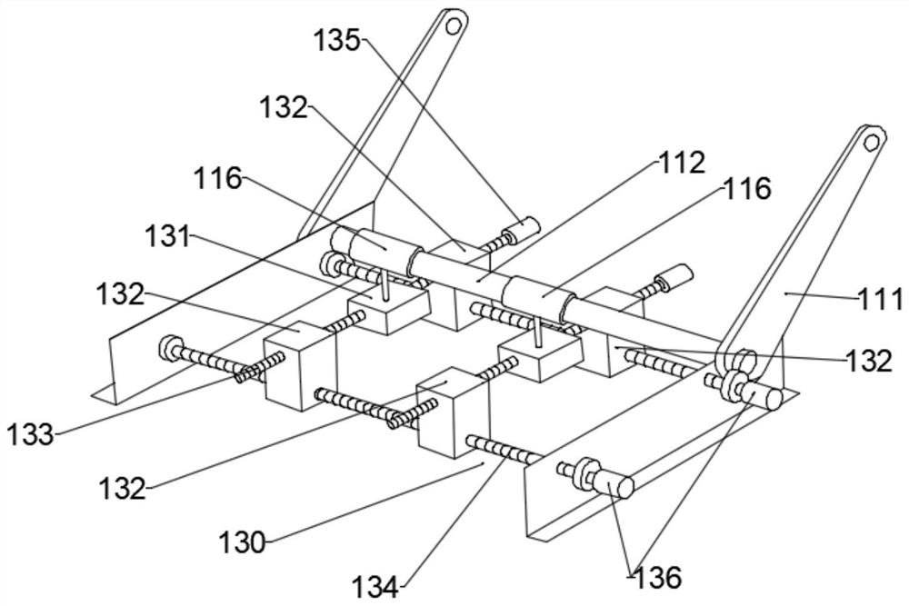
The invention discloses a swing arm floor tile laying device, and relates to the technical field of tile laying equipment. The swing arm floor tile laying device comprises a tile laying vehicle and a tile conveying vehicle, the tile laying vehicle comprises a laying mechanism, a clamping mechanism, an adjusting mechanism and a tile laying vehicle body, the laying mechanism comprises swing arms symmetrically arranged on the two sides of the tile laying vehicle body, one ends of the swing arms on the two sides of the tile laying vehicle body are connected with the clamping mechanism, and the other ends of the swing arms on the two sides of the tile laying vehicle body are connected with a driving shaft close to the top end in the tile laying vehicle body; the clamping mechanism comprises a suction cup assembly used for sucking tiles; the adjusting mechanism comprises a first sliding block connected with the driving shaft, second sliding blocks arranged on the two sides of the first sliding block, and pulley assemblies used for sliding the first sliding block and the second sliding blocks; and the tile conveying vehicle comprises a tile conveying vehicle body, and a male cone arranged on the tile conveying vehicle body and a female cone arranged on the tile laying vehicle body are matched and connected through a magnetic attraction structure. Tile laying can be completed efficiently, and the tile laying position is more accurate.

Description

technical field [0001] The invention relates to the technical field of brick laying equipment, in particular to a swing arm floor brick laying device. Background technique [0002] Floor tile laying is an indispensable part of decoration. At present, floor tile laying is mostly done manually. This method of laying is inefficient. Therefore, brick laying vehicles have appeared on the market to replace manual laying of floor tiles, thereby improving efficiency. [0003] However, when using a tile-laying vehicle to lay floor tiles, errors will inevitably occur. At present, there is no tile-laying vehicle that can solve the adjustment error of the tile-laying vehicle when laying floor tiles, and when laying floor tiles, the gap between the floor tiles The gap does not have only one width, and the existing tile-laying vehicle cannot adjust the gap width between the floor tiles and the floor tiles during the laying process. [0004] When using a brick-laying truck to lay, it is a...

Claims


Application Information

Patent Timeline
Patent Type & Authority Applications(China)
IPC IPC(8): E04F21/22
CPCE04F21/22
Inventor 郭建文邝磊郭建功
Owner 中一北工科技发展股份有限公司
Why Eureka
Try Eureka