Eureka AIR delivers breakthrough ideas for toughest innovation challenges, trusted by R&D personnel around the world.

Radar system capable of monitoring rotating speed of motor, implementation method and radar equipment

A technology of motor speed and radar system, applied in the field of radar, can solve the problems of slow feedback pulse edge, large divergence angle of emitted light, timing error, etc., to achieve the effect of ensuring stability and reliability, accurate and efficient monitoring, and reducing speed measurement error

Pending Publication Date: 2021-11-02
FOSHAN HUAGUO OPTICAL
View PDF0 Cites 0 Cited by
  • Summary
  • Abstract
  • Description
  • Claims
  • Application Information

AI Technical Summary

Problems solved by technology

[0004] However, this photogate speed measurement method has the following disadvantages: firstly, the divergence angle of the light emitted by the photogate is relatively large, so that the edge of the generated feedback pulse is relatively slow, the edge monitoring accuracy is not high, and it is easy to cause the emitted light to pass through both on the code wheel at the same time. Gaps in bars, resulting in timing errors
In addition, the machining error of the code disc itself will also affect the timing of the photoelectric gate feedback pulse edge, thereby reducing the accuracy of pulse edge timing and speed measurement
However, in the existing laser radar technology applications, no technical solutions for the above problems have been given.

Method used


Image

  • Radar system capable of monitoring rotating speed of motor, implementation method and radar equipment
  • Radar system capable of monitoring rotating speed of motor, implementation method and radar equipment
  • Radar system capable of monitoring rotating speed of motor, implementation method and radar equipment

Examples


Embodiment Construction

[0049] The present invention will be further described in detail below in conjunction with the accompanying drawings and specific embodiments. For the step numbers in the following embodiments, it is only set for the convenience of illustration and description, and the order between the steps is not limited in any way. The execution order of each step in the embodiments can be adapted according to the understanding of those skilled in the art sexual adjustment.

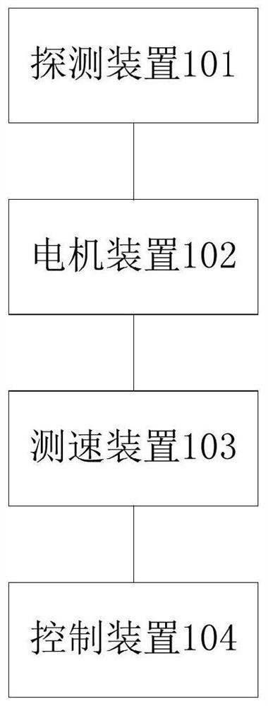
[0050] refer to figure 1 , an embodiment of the present invention provides a radar system capable of monitoring motor speed, including:

[0051] The detection device 101 is used for transmitting and receiving laser signals;

[0052] The motor device 102 is used to carry the detection device 101 to realize the rotational emission and reception of laser signals;

[0053] a speed measuring device 103, configured to detect the rotational speed of the motor device 102, and send the rotational speed information to the co...


PUM


Abstract

The invention discloses a radar system capable of monitoring the rotating speed of a motor, an implementation method and radar equipment, wherein the radar system comprises a detection device, a motor device, a speed measurement device and a control device; the speed measurement device comprises a coded disc, a diaphragm and a photoelectric door; the diaphragm can limit the divergence degree of speed measurement laser beams emitted by the photoelectric door, and the edge of received feedback pulses is steeper. According to the method, during speed measurement, the time difference between the rising edge and the falling edge in the feedback pulse sequence is monitored at the same time, so that the rotating speed of the motor is calculated, and the speed measurement error caused by the machining error of code disc hole opening can be reduced to the maximum extent. The radar equipment comprises the radar system. By using the radar system disclosed by the invention, the monitoring of the rotation speed of the motor in the laser radar system can be more accurate and efficient, and the stability and reliability of the operation of the laser radar system can be ensured. The radar system and the radar equipment can be widely applied to the technical field of radars.

Description

technical field [0001] The invention relates to the technical field of radar, in particular to a radar system capable of monitoring the rotational speed of a motor, its realization method and radar equipment. Background technique [0002] Lidar technology is a radar system that emits laser beams to detect characteristic quantities such as the position and speed of targets. Compared with conventional microwave radar, laser radar uses laser beams, and its working frequency is much higher than that of microwaves, so it brings advantages such as high resolution, good concealment, strong anti-active interference ability, small size and light weight. and other advantages. Existing lidar technology is mainly used in industries such as robotic equipment, car assisted driving and drones. At present, its laser emitting and receiving technology, the communication technology design between the rotating end and the control module have gradually matured, and related products have gradua...

Claims


Application Information

Patent Timeline
IPC IPC(8): G01S7/481G01S7/483G01S17/58G01S17/88
CPCG01S7/481G01S7/483G01S17/58G01S17/88
Inventor 陈耀明周義隆郭建兵朱清林
Owner FOSHAN HUAGUO OPTICAL
Why Eureka
Eureka Blog
Learn More