Direct speed transition fairing method based on trigonometric function acceleration and deceleration control

A technology of acceleration and deceleration control and trigonometric functions, which is applied in the field of CNC machining path smoothing, can solve the problems affecting real-time machining, the kinematic performance of corners, the limited improvement of smoothness, and the increase of algorithm complexity, so as to improve the kinematics. performance, guaranteeing higher-order continuity, and the effect of solving geometric discontinuity problems

Pending Publication Date: 2021-11-02
TIANJIN UNIV
View PDF0 Cites 0 Cited by
  • Summary
  • Abstract
  • Description
  • Claims
  • Application Information

AI Technical Summary

Problems solved by technology

The complexity of the two-step transition algorithm is related to the optimized tool path; therefore, if you want to obtain a higher path continuity, the complexity of the algorithm will inevitably increase, which affects the real-time performance of processing
At the same time, the linear and geometric transition scheme of the traditional two-step method has limited improvement in the kinematic performance and smoothness of corners.

Method used


Image

  • Direct speed transition fairing method based on trigonometric function acceleration and deceleration control
  • Direct speed transition fairing method based on trigonometric function acceleration and deceleration control
  • Direct speed transition fairing method based on trigonometric function acceleration and deceleration control

Examples


Embodiment Construction

[0062] In order to further understand the content of the invention, features and effects of the present invention, the following embodiments are listed herewith, and are described in detail as follows in conjunction with the accompanying drawings:

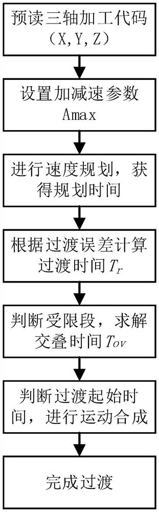
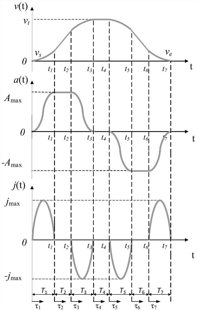
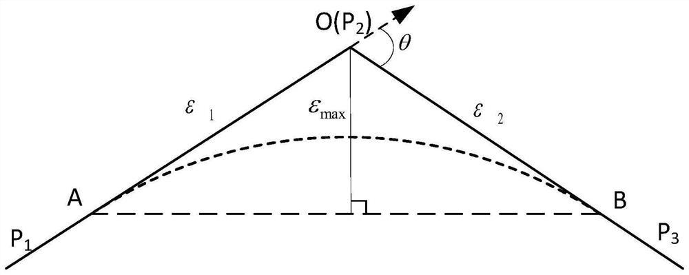
[0063] See Figure 1 to Figure 8 , the technical scheme adopted by the present invention to solve the technical problems existing in the known technology is: a direct speed transition smoothing method based on the acceleration and deceleration control of trigonometric functions, read the coordinates of the processing code point, and set the original processing path to be a continuous It is composed of micro-segments connected by points. The length of the micro-segments and the angle between adjacent micro-segments are calculated by the point coordinates; The transition stage is in the deceleration stage of the previous micro-line segment and the acceleration stage of the next micro-line segment. Sin(2x) is used as the basis functio...


PUM


Abstract

The invention discloses a direct speed transition fairing method based on trigonometric function acceleration and deceleration control. The method comprises the following steps that a processing code point position coordinate is read, an original processing path is set to be composed of micro line segments connected by continuous point positions, and the length of the micro line segments and an included angle between the adjacent micro line segments are calculated according to point position coordinates; the machining process of each micro line segment is divided into a plurality of segments according to an acceleration function, transition stages of corners of two adjacent micro line segments are located in a deceleration stage of the previous micro line segment and an acceleration stage of the next micro line segment, sin(2x) is adopted as a basis function of jerk to establish an acceleration and deceleration model, and the maximum acceleration and acceleration and deceleration parameters are set; and according to the maximum allowable machining error, the overlapping mixing transition time and the transition starting time of the micro-line segment corner are solved, motion synthesis is carried out, and therefore the machining path after fairing optimization is obtained. The method is advantaged in that one-step transition can be achieved, smooth transition of three-axis motion inflection points can be achieved under the condition that high motion continuity is guaranteed, and high-order continuity of motion in the machining process is guaranteed.

Description

technical field [0001] The invention relates to a method for smoothing a numerically controlled machining path, in particular to a direct speed transition smoothing method based on the acceleration and deceleration control of trigonometric functions. Background technique [0002] At present, CNC machine tools are a very important part of modern machining, which can realize high-speed, high-precision and efficient machining. In the CNC machining process, the smoothing of the tool path and the flexible acceleration and deceleration have become the focus of improving accuracy and efficiency. The micro-segment composed of G01 code points has been widely used in the processing of complex geometric parts. The advantage of the micro-segment is that it can describe the shape of the geometric part well, but at the connection of the micro-segment, there will be differences in the path direction. Continuity and discontinuity of curvature, which will lead to greater vibration during ma...

Claims


Application Information

Patent Timeline
Patent Type & Authority Applications(China)
IPC IPC(8): G05B19/416
CPCG05B19/4163G05B2219/36521
Inventor 王太勇陈木正刘杨帆张永宾邢洁济
Owner TIANJIN UNIV
Why Eureka
Try Eureka