Three-axis micro-line segment direct speed transition method based on trigonometric function acceleration and deceleration control

A technology of acceleration and deceleration control and trigonometric functions, applied in digital control, program control, electrical program control, etc., can solve problems such as limited kinematic performance and smoothness improvement at corners, increasing algorithm complexity, and affecting real-time performance. Achieve the effects of ensuring high-order continuity, solving geometric discontinuity problems, and improving processing efficiency

Active Publication Date: 2020-11-20
TIANJIN UNIV
View PDF6 Cites 6 Cited by
  • Summary
  • Abstract
  • Description
  • Claims
  • Application Information

AI Technical Summary

Problems solved by technology

The complexity and accuracy of the two-step transition algorithm are related to the type of transition curve inserted. The more complex the transition curve algorithm is inserted, the higher the path continuity will be obtained, and the complexity of the algorithm will be increased, which will affect the real-time performance. The linear and geometric transition scheme of the traditional two-step method has limited improvement in the kinematic performance and smoothness of corners

Method used


Image

  • Three-axis micro-line segment direct speed transition method based on trigonometric function acceleration and deceleration control
  • Three-axis micro-line segment direct speed transition method based on trigonometric function acceleration and deceleration control
  • Three-axis micro-line segment direct speed transition method based on trigonometric function acceleration and deceleration control

Examples


Embodiment Construction

[0033] In order to further understand the invention content, characteristics and effects of the present invention, the following embodiments are enumerated hereby, and detailed descriptions are as follows in conjunction with the accompanying drawings:

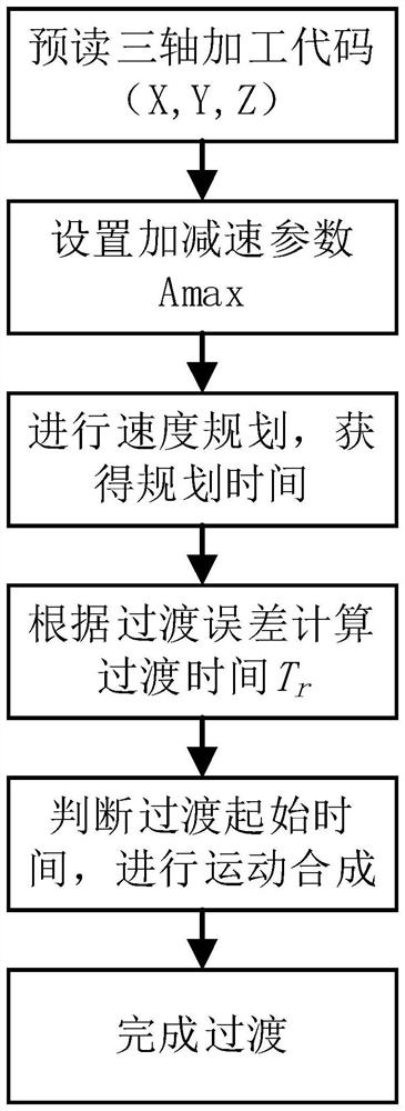
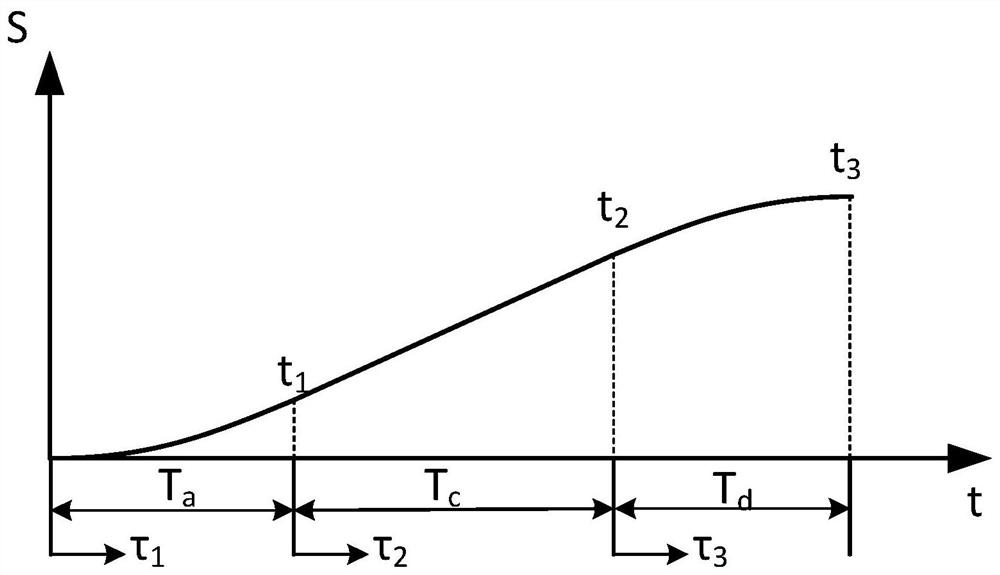
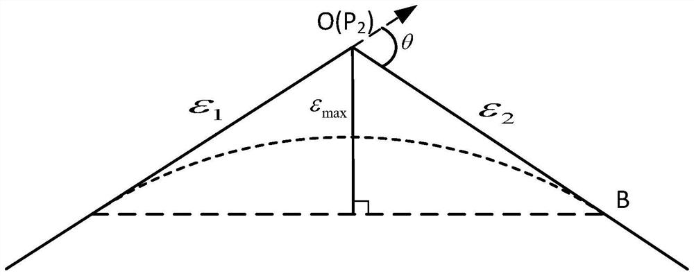
[0034] See Figure 1 to Figure 7 , a direct speed transition method for three-axis micro-line segments based on trigonometric functions, read the point coordinates of the three-axis machining code, form the processing path by the micro-line segments connected by continuous points, and obtain the length of each micro-line segment and any The rotation angle between two adjacent micro-line segments; for the adjacent two micro-line segments with a rotation angle greater than 0°, a trigonometric function acceleration and deceleration model is established, and each micro-line segment is divided into an acceleration segment, a constant velocity segment and a deceleration segment, and the interpolation trigonometric function is added T...


PUM


Abstract

The invention discloses a three-axis micro-line segment direct speed transition method based on trigonometric function acceleration and deceleration control. The method comprises the steps of obtaining the length of each micro-line segment and the rotation angle between any two adjacent micro-line segments through machining code point position coordinates; establishing a trigonometric function acceleration and deceleration model for two adjacent micro line segments of which the rotation angle is than 0 degree to obtain interpolation speed functions and interpolation displacement functions of the acceleration segments, the constant speed segments and the deceleration segments of the corresponding micro line segments; carrying out speed planning to determine interpolation time of each segment; setting the maximum transition error of two adjacent micro-line segments, solving the maximum transition line segment length, and setting the transition line segment lengths of the two micro-line segments to be equal and less than or equal to the minimum value of the first micro-line segment deceleration segment length and the second micro-line segment acceleration segment length; determining atransition starting moment according to the transition line segment length; calculating transition time through an interpolation displacement function; and synthesizing the motions of the transitionline segments of two adjacent micro-line segments to obtain a transition path. According to the method, the complexity of an algorithm is reduced, and meanwhile, the corner machining efficiency is improved.

Description

technical field [0001] The invention relates to the technical field of numerical control in mechanical manufacturing engineering technology, in particular to a direct speed transition method for three-axis micro-line segments based on trigonometric function acceleration and deceleration control. Background technique [0002] At present, CNC machine tools are widely used in the machining industry due to their high production efficiency. In modern industrial product modeling design, CAM software can convert two-dimensional or three-dimensional model information into the form of continuous micro-line segments. However, due to the discontinuity of the continuous micro-line segment trajectory, the CNC needs to reduce the speed at the corner of the adjacent micro-line segment to meet the processing requirements. In this way, the processing efficiency is greatly reduced, and frequent acceleration and deceleration lead to vibration of the machine tool. Vibration makes the machine t...

Claims


Application Information

Patent Timeline
Patent Type & Authority Applications(China)
IPC IPC(8): G05B19/416
CPCG05B19/4163G05B2219/36521
Inventor 王太勇刘杨帆张永宾彭鹏韩文灯
Owner TIANJIN UNIV
Why Eureka
Try Eureka