Novel combined arc extinguishing lightning protection device

A lightning protection device and arc extinguishing technology, which is applied to electrical components, spark gaps, spark gap components, etc. It will not be destroyed, the arc extinguishing speed is fast, and the effect of reducing the residual pressure value

Pending Publication Date: 2021-11-02
南宁超伏电气科技有限公司
View PDF0 Cites 2 Cited by
  • Summary
  • Abstract
  • Description
  • Claims
  • Application Information

AI Technical Summary

Problems solved by technology

[0004] The purpose of the present invention is to provide a new type of combined arc extinguishing and lightning protection device to solve the technical problems of the existing lightning protection, arc extinguishing attenuation, lightning current amplitude, and slow arc extinguishing speed.

Method used


Image

  • Novel combined arc extinguishing lightning protection device
  • Novel combined arc extinguishing lightning protection device
  • Novel combined arc extinguishing lightning protection device

Examples


Embodiment 1

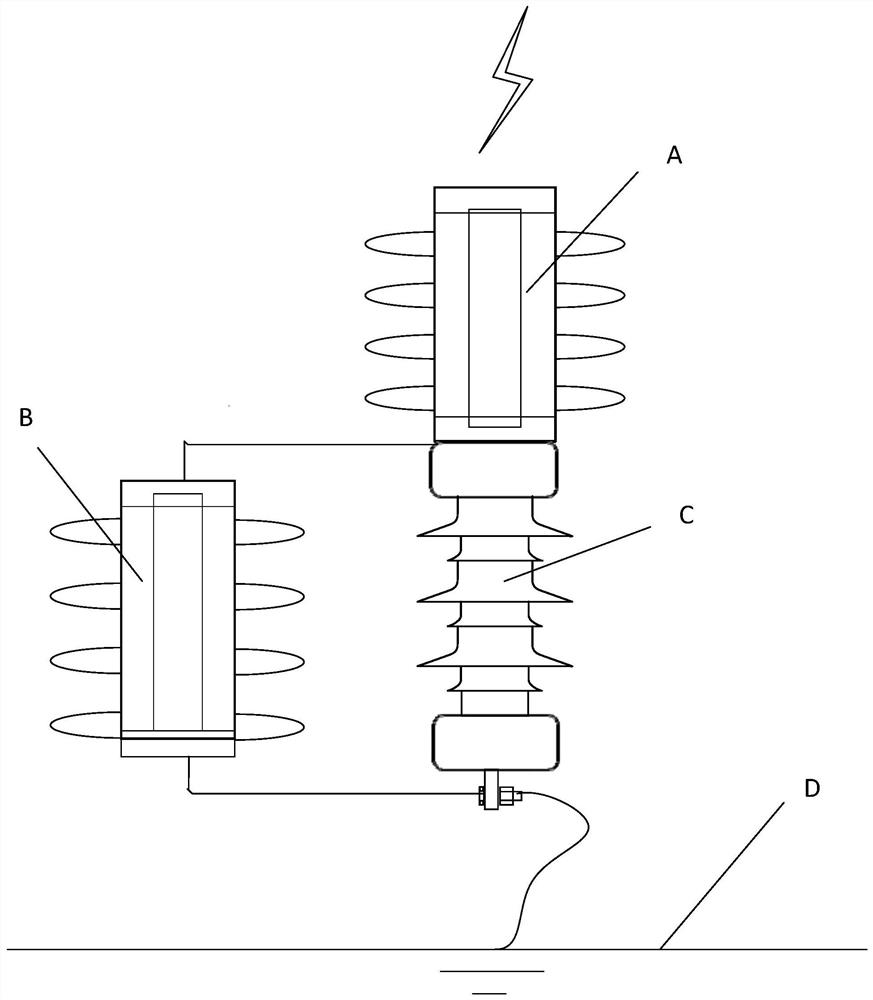
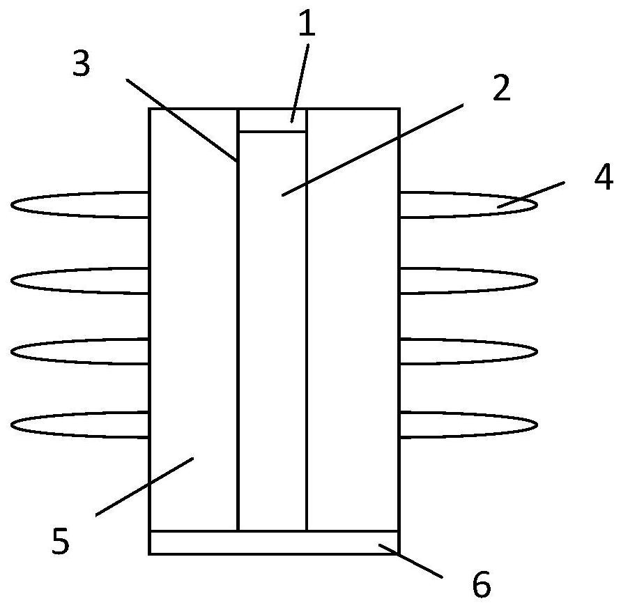
[0040] Such as figure 1 and Figure 3-4 As shown, a new type of combined arc extinguishing and lightning protection device includes an end arc extinguishing unit A, a sealed arc extinguishing unit B and an insulator string C, the sealed arc extinguishing unit B is arranged in parallel on the insulator string C, and the end arc extinguishing unit A is set on the upper end of the insulator string C, and is electrically connected to the metal parts at the end of the insulator string C, and the bottom of the insulator string C is grounded. The arc enters from one end of the series insulator device, and the basic arc is completely cut off at this stage without re-ignition. If the arc is not completely cut off after the arc is extinguished at this stage, it will be completely cut off through the parallel device with the insulator string, and the remaining arc energy will enter the ground through the grounding channel of the conductive electrode, which greatly protects the safety of...

Embodiment 2

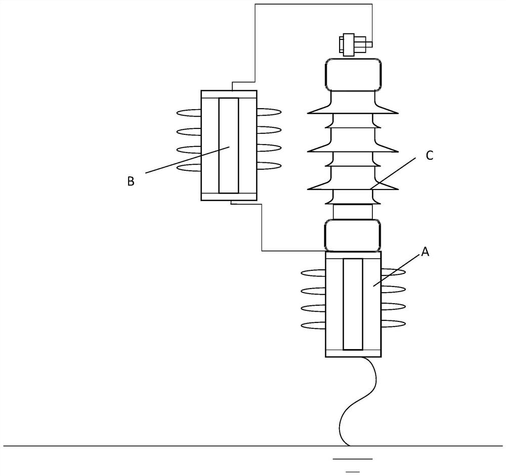
[0058] Such as figure 2 As shown, the difference between this embodiment and Embodiment 1 is that the end arc extinguishing unit A is installed at the bottom of the insulator string C, and at the same time the bottom of the end arc extinguishing unit A is directly grounded, and then the top of the end arc extinguishing unit A is also Connect to one end of sealed arc extinguishing unit B. In the event of a similar electric shock, the lightning arc first passes through the sealed arc extinguishing unit B from the top of the insulator string C, and then to the end arc extinguishing unit A to achieve breakdown at two places and arc extinguishing at two places, realizing one channel Two points are extinguished at the same time.

[0059] When the lightning current strikes the line, the liquid arc extinguishing device introduces the arc into it through insulation cooperation, avoiding the flashover of the arc passing through the insulator, and through the combination of series and ...


PUM


Abstract

The invention discloses a novel combined arc extinguishing lightning protection device, and belongs to the technical field of lightning protection and arc extinguishing, the novel combined arc extinguishing lightning protection device comprises an end portion arc extinguishing unit, a sealing arc extinguishing unit and an insulator chain, the sealing arc extinguishing unit is arranged on the insulator chain in parallel, and the end portion arc extinguishing unit is arranged at the upper end or the lower end of the insulator chain and is electrically connected with an insulator chain end portion metal piece. When the end portion arc extinguishing unit is arranged at the upper end of the insulator string, the bottom of the insulator string is grounded, and when the end portion arc extinguishing unit is arranged at the bottom of the insulator string, the bottom of the end portion arc extinguishing unit is grounded. The arc extinguishing integrality is high, reignition is avoided, the arc is integrally cut off at the same time instead of being cut off in sections, and the medium recovery speed tends to be infinite and reaches the limit of itself, so that the arc extinguishing speed is high, and the reignition is avoided.

Description

technical field [0001] The invention relates to the field, in particular to a novel combined arc extinguishing and lightning protection device. Background technique [0002] Lightning strikes will bring different forms of damage and destruction to power facilities, and thundercloud discharge will cause lightning strike overvoltage in the power system. Lightning strike overvoltage may cause damage to insulators and transmission lines; the impact flashover caused by lightning strikes on transmission lines will cause flashover of line insulators, and then generate a large power frequency current, damage insulator strings and fittings, and cause line accidents; Electric shock on the transmission line or lightning protection line may cause broken strands or even rupture, making the transmission work impossible. [0003] The existing lightning protection and arc extinguishing device can make the volt-second characteristics of the active arc extinguishing parallel gap more flat, b...

Claims


Application Information

Patent Timeline
Patent Type & Authority Applications(China)
IPC IPC(8): H01T1/02H01T1/08
Inventor 王巨丰王嬿蕾卢杨骆耀敬宋永锋李浩何琪文贾征浩陈宇宁
Owner 南宁超伏电气科技有限公司
Why Eureka
Try Eureka