
Splicing box and splicing display screen

A display screen and cabinet technology, which is applied to the housing with display/control unit, cabinet/cabinet/drawer components, instruments, etc., which can solve the problems affecting the display effect of the spliced ​​display screen and avoid the impact Display effect, meet the requirements of multi-screen display, and ensure the effect of texture

Inactive Publication Date: 2021-11-02
TCL CHINA STAR OPTOELECTRONICS TECH CO LTD
View PDF10 Cites 0 Cited by
  • Summary
  • Abstract
  • Description
  • Claims
  • Application Information

AI Technical Summary

Problems solved by technology

[0004] The purpose of the present invention is to provide a splicing box and a splicing display screen, which can solve the problems of height difference or gap between the cabinets existing in the existing splicing display screen, which affects the display effect of the splicing display screen

Method used


Image

  • Splicing box and splicing display screen
  • Splicing box and splicing display screen
  • Splicing box and splicing display screen

Examples


Embodiment 1

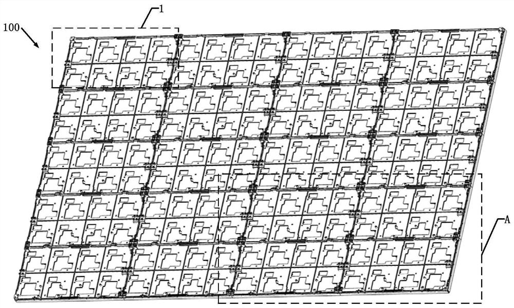
[0046] like figure 1 As shown, this embodiment provides a splice box 100 . The spliced ​​box 100 includes a plurality of box bodies 1 spliced ​​and fixed to each other. In this embodiment, the cabinets 1 are arranged in 5 rows and 4 columns. In other embodiments, the number of rows and columns of the cabinet 1 can be adjusted according to actual needs.

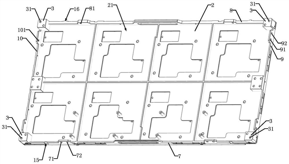
[0047] like figure 2 As shown, each of the boxes 1 includes: a base 2 and a connecting base 3 .

[0048] like figure 2As shown, the base 2 has a first surface 21 and a second surface (not shown) disposed opposite to each other.

[0049] like figure 2 As shown, the connecting base 3 protrudes from the first surface 21 of the base 2 and is located at four corners of the base 2 . Each of the connecting bases 3 is provided with at least one first fastening hole 31 . In this embodiment, each of the connecting bases 3 is provided with two first fastening holes 31 . In this embodiment, the first fastening holes 31 are scre...

Embodiment 2

[0070] This embodiment also provides a spliced ​​display screen. The spliced ​​display screen includes the splicing box 100 of Embodiment 1 and a plurality of display units.

[0071] Wherein, the display unit array is arranged on the second surface of the box body 1 . The display unit includes: one of a mini LED display unit, a micro LED display unit and an OLED display unit. In this embodiment, the display unit is a mini LED display unit.

[0072] During the assembly process of multiple boxes 1, when there is a height difference between the second surface of a certain box 1 and the second surface of other boxes 1, adjust the first adjustment member 6 at the box 1 to adjust the The box body 1 is lifted or lowered, so as to adjust the height of the second surface of the box body 1, so that the second surface of the box body 1 is on the same plane as the second surfaces of other boxes The display units on the second surface of 1 are in the same plane. As a result, the screen...


PUM


Abstract

The invention relates to a splicing box and a splicing display screen. In the process of splicing and assembling a plurality of box bodies, when a height difference exists between the second surface of a certain box body and the second surfaces of other box bodies, a first adjusting piece at the box body is adjusted to jack up or put down the box body so that the height of the second surface of the box body is adjusted; and the second surface of the box body and the second surfaces of other box bodies are located on the same plane, the display units located on the second surface of the box body are located on the same plane, and therefore under the small area, the screen resolution can be improved, the picture texture is guaranteed, and the requirement for close-range watching of a user is met.

Description

technical field [0001] The present application relates to the technical field of splicing display, in particular to a splicing box and a splicing display. Background technique [0002] At this stage, due to the improvement of our country's monitoring technology level and data collection capabilities to a certain extent. Whether the display terminal can accurately present the collected data on the display wall in a timely manner is directly related to the rationality of the superior department's decision-making, which is very important. In order to meet the needs of the market, the technicians of the display terminal need to improve the existing technology to make it develop in the direction of seamlessness and high-definition. It came into being. [0003] However, the current processing technology cannot guarantee the flatness of the splicing box of the spliced ​​display to be zero, and in the process of splicing and assembling multiple boxes, there will be height differen...

Claims


Application Information

Patent Timeline
Patent Type & Authority Applications(China)
IPC IPC(8): H05K5/00H05K5/02G09F9/302
CPCH05K5/0021H05K5/0017H05K5/0217G09F9/302G09F9/3026G09F9/33G09F9/35
Inventor 邹广南
Owner TCL CHINA STAR OPTOELECTRONICS TECH CO LTD
Learn More