Industrial heating radiator painting equipment

An industrial technology for heat sinks, applied in the field of heat sink painting equipment, can solve the problems of secondary painting, uneven paint on heating heat sinks, and affecting the appearance of heating heat sinks

Active Publication Date: 2021-11-05
佛山市泓力智能设备有限公司
View PDF7 Cites 0 Cited by
  • Summary
  • Abstract
  • Description
  • Claims
  • Application Information

AI Technical Summary

Problems solved by technology

[0004] In order to overcome the manual use of painting tools to paint the radiator fins, due to human factors, it is easy to make the paint on the radiator fins uneven, affecting the appearance of the radiator fins, and it is easy to cause secondary painting, which affects the progress of the painting process However, the technical problem of the present invention is to provide an industrial heating radiator painting equipment capable of automatic painting, better painting effect and convenient use

Method used


Image

  • Industrial heating radiator painting equipment
  • Industrial heating radiator painting equipment
  • Industrial heating radiator painting equipment

Examples


Embodiment 1

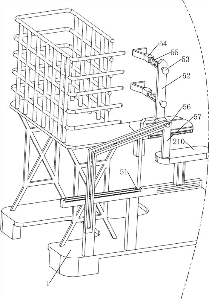
[0072] Industrial heating heat sink paint equipment, such as figure 1As shown, including the base 1, the rise mechanism 2 and the painting mechanism 3, the base 1 is provided with a spray mechanism 3 at the top of the rise mechanism 2.

[0073] When people need to laminate the heating tile, the industrial heating heat sink paint can first be placed on the pedestal 1, and the paint is poured into the paint mechanism 3, and then start the rise mechanism 2, the rise mechanism 2 moves the painting mechanism 3 upward movement so that the painting mechanism 3 can paint the heating heat sink, and when the rise mechanism 2 is moved downward, the painting mechanism 3 can be again refurbished. After the heat sink, when the rise mechanism 2 is reset down, the paint mechanism 3 stops paint on the heating heat sink, and then closing the raised mechanism 2.

Embodiment 2

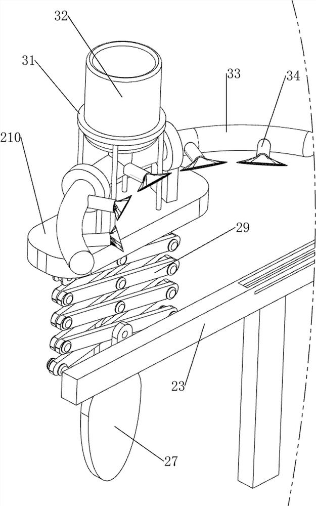
[0075] On the basis of Example 1, such as figure 2 and image 3 As shown, the rise mechanism 2 includes a first support frame 21, a motor 22, a first fixing block 23, a second fixing block 24, a housing 25, a rotating shaft 26, a cam 27, a top block 28, a folding frame 29, a second support. The frame 210 and the first slider 211, and the seat 1 are provided with a first support frame 21, and a motor 22 is attached to the top of the first support frame 21, and the first fixed block 23 is provided on the top of the base 1. The base 1 is provided with a second fixing block 24 on the upper right portion. The first support frame 21 is provided with a bearing housing 25, and the output shaft on both sides of the motor 22 is connected to the housing 25, respectively. There is a cam 27 in the outer side of the rotating shaft 26, and the left side and the second fixing block 24 of the first fixing block 23 are provided with a folded frame 29, and the lower side of the two folded frames 29 i...

Embodiment 3

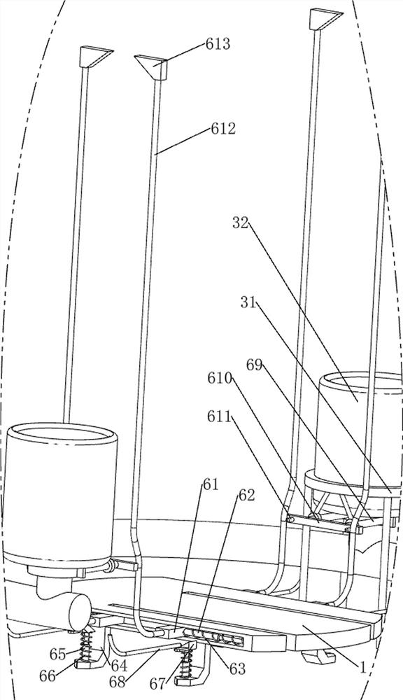
[0080] On the basis of Example 2, such as Figure 4 - Figure 7 As shown, there is also a push mechanism 4, and the pincer portion includes a first fixing plate 41, a first stretch rod 42, a first push plate 43, and a first spring 44, and the base 1 is provided. The first fixing plate 41, both sides of the left and right sides of the first fixing plate 41 are provided with a first retracting rod 42, and there is a first push plate 43, two first stretch rods. 42 is around the first spring 44, and both ends of the first spring 44 are connected to the first push plate 43 and the first fixing plate 41, respectively.

[0081] After the plurality of heating heat sinks are placed on the base 1, the first push plate 43 is moved backward due to the pressure of the heating heat sink, so that the first retracting rod 42 is contracted, the first spring 44 is compressed, when people After the first spring 44 is reset, the first push plate 43 is moved forward due to the reduction of the pressure,...


PUM


Abstract

The invention relates to radiator painting equipment, and particularly relates to industrial heating radiator painting equipment. The industrial heating radiator painting equipment can achieve automatic painting, is good in painting effect and convenient to use. The industrial heating radiator painting equipment comprises a base, a rising mechanism and a paint spraying mechanism, wherein the rising mechanism is arranged on the base, and the paint spraying mechanism is arranged at the top of the rising mechanism. According to the industrial heating radiator painting equipment, the rising mechanism and the paint spraying mechanism are arranged, the rising mechanism is matched with the paint spraying mechanism, the rising mechanism operates to drive the paint spraying mechanism to move up and down, a heating radiator is painted, and the rising and paint spraying effects are achieved; and a pushing mechanism and a feeding mechanism are arranged, the pushing mechanism is matched with the feeding mechanism, the feeding mechanism can push out the heating radiator in the pushing mechanism, and the pushing and feeding effects are achieved.

Description

Technical field [0001] The present invention relates to a heat sink lacquer device, and more particularly to an industrial heating heat-dissipating device. Background technique [0002] The heating heat sink is when the heat medium having a higher temperature flows through the heating heat sink, the heat carried by the heat medium is constantly transmitting the temperature of the temperature with a lower temperature of the temperature, thereby achieving thermal difference transmission, with society Constantly developing, the application of heating heat sink is also more extensive, so the demand for heating heat sinks is increasing, and most warm gas tile manufacturing plants in the market are usually artificial use of lacquer tools to paint the heating heat sink. Due to human resources. Factors, it is easy to make the heating heat sink is uneven, affecting the aesthetics of the heating heat sink, and is easy to cause secondary paint, affecting the working progress of the paint. ...

Claims


Application Information

Patent Timeline
Patent Type & Authority Applications(China)
IPC IPC(8): B05B13/04B05B13/02B05B15/00
CPCB05B13/041B05B13/0221B05B15/00Y02P70/10
Inventor 周俊鹏
Owner 佛山市泓力智能设备有限公司
Why Eureka
Try Eureka