A steel bending device

A bending device and steel technology, applied in the field of metal processing, can solve problems such as inconvenience in taking steel bars, and achieve the effects of improving service life and processing efficiency

Active Publication Date: 2021-11-30
南通佰瑞利电动工具有限公司
View PDF6 Cites 0 Cited by
  • Summary
  • Abstract
  • Description
  • Claims
  • Application Information

AI Technical Summary

Problems solved by technology

[0006] Aiming at the deficiencies of the prior art, the present invention provides a steel bending device, which solves the problem that it is inconvenient for workers to take the processed steel bars when the device is processing the steel bars, improves the processing efficiency, and improves the processing efficiency. When bending, the outer surface of the bending area is cushioned, and the purpose of clamping steel bars of different diameters is realized, which avoids the abrasion of the steel bar surface caused by external tools in the process of bending the steel bars, and improves the bending efficiency. Service life of steel bars after folding

Method used


Image

  • A steel bending device
  • A steel bending device
  • A steel bending device

Examples


Embodiment 1

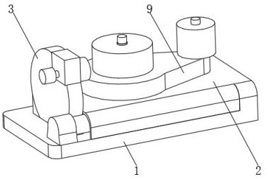
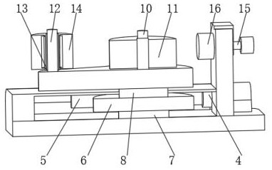
[0029] see Figure 1-4 , the present invention provides a technical solution: a steel bending device, including a bottom plate 1, the top of the bottom plate 1 is fixedly connected with a dust cover 2, and the side of the bottom plate 1 close to the dust cover 2 is fixedly connected with a fixed side plate 3, One side of the fixed side plate 3 is fixedly connected with a hydraulic telescopic rod 4, and one end of the hydraulic telescopic rod 4 runs through the fixed side plate 3 and is fixedly connected with a rack 5, and one side of the rack 5 is meshed with a gear 6, and the bottom of the gear 6 is rotated The seat 7 is rotationally connected with the bottom plate 1, the top of the gear 6 is fixedly connected with a connection block 8, the top of the connection block 8 penetrates the dust cover 2 and is fixedly connected with a turntable 9, and the side of the turntable 9 away from the connection block 8 is fixedly connected with a connection rod 10 The outer side of the con...

Embodiment 2

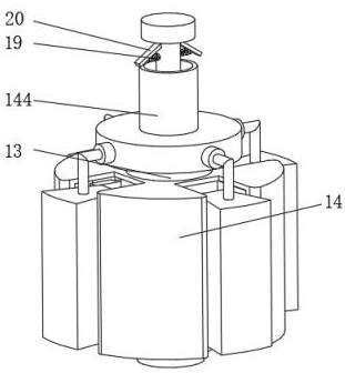
[0037] see Figure 1-5 , the present invention provides a technical solution: on the basis of Embodiment 1, one end of the electric push rod 15 penetrates through the fixed side plate 3 and is fixedly connected with a clamping device 16, the clamping device 16 includes a bottom frame 161, and the outside of the bottom frame 161 Fixedly connected with the electric push rod 15 , a telescopic spring 162 is mounted symmetrically on the inner bottom of the bottom frame 161 , and a top plate 163 is fixedly connected to the end of the telescopic spring 162 away from the bottom frame 161 .

[0038] One side of the top plate 163 is fixedly connected with an elastic rod 164, one end of the elastic rod 164 runs through one side of the top plate 163, an elastic air bag 165 is installed inside the bottom frame 161, and one side of the top plate 163 is uniformly provided with round holes 166, and the round holes 166 An elastic rubber sheet 167 is fixedly connected to the inner wall of the i...


PUM


Abstract

The invention discloses a steel bending device, which comprises a bottom plate, a dust cover is fixedly connected to the top of the bottom plate, a fixed side plate is fixedly connected to the side of the bottom plate close to the dust cover, and a fixed side plate is fixedly connected to one side of the fixed side plate. The side is fixedly connected with a hydraulic telescopic rod, and one end of the hydraulic telescopic rod penetrates the fixed side plate and is fixedly connected with a rack. One side of the rack is meshed with a gear, and the bottom of the gear is rotatably connected with the bottom plate through a rotating seat. The top of the gear is fixedly connected with a connecting block, and the top of the connecting block penetrates the dust cover and is fixedly connected with a turntable. There is a bending limit disk, and a round rod is installed on the top of the rotating disk away from the connecting rod. The invention relates to the technical field of metal processing. The steel bending device can facilitate the taking of the processed steel bar, and improves the processing efficiency.

Description

technical field [0001] The invention relates to the technical field of metal processing, in particular to a steel material bending device. Background technique [0002] Due to its excellent mechanical properties and electrical conductivity, steel is widely used in industries such as electric power, construction, and machining. During use, it is often necessary to bend steel into specific shapes according to different uses. The bending methods of steel mainly include manual bending and mechanical bending, but manual bending requires high strength and is dangerous; traditional mechanical bending devices are inefficient, and the uniformity of steel bending is not ideal . [0003] For example, Chinese patent CN111842570A proposes a bending device, the bending device includes: a base, at least one mounting frame is arranged on the base; wheel; extrusion wheel, which is slidably arranged on the mounting frame, and cooperates with the driving wheel to clamp the material; bending ...

Claims


Application Information

Patent Timeline
Patent Type & Authority Patents(China)
IPC IPC(8): B21F1/00
Inventor 季威威
Owner 南通佰瑞利电动工具有限公司
Why Eureka
Try Eureka