A support method for surrounding rock of soft rock roadway under high impact geocompressive stress
A compressive stress, high impact technology, applied in underground chambers, tunnels, earthwork drilling and mining, etc., can solve the problems of small opening of cracks, deformation and damage of surrounding rock, and difficulty in timely support, so as to facilitate repeated use and improve The effect of porosity
- Summary
- Abstract
- Description
- Claims
- Application Information
AI Technical Summary
Problems solved by technology
Method used
Image
Examples
Embodiment 1
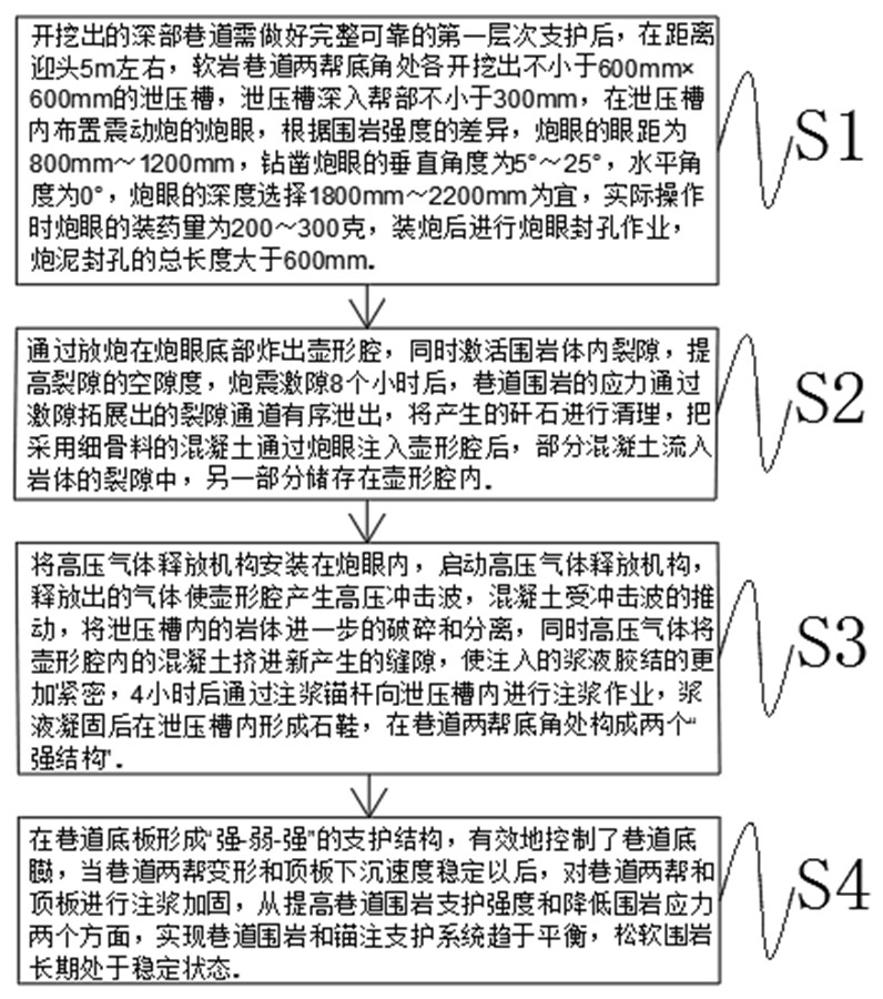
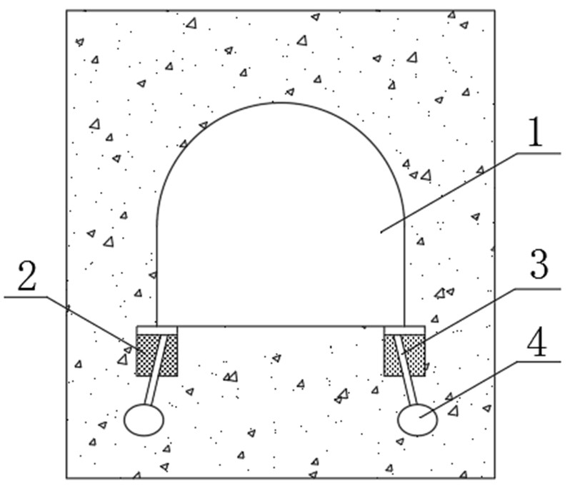
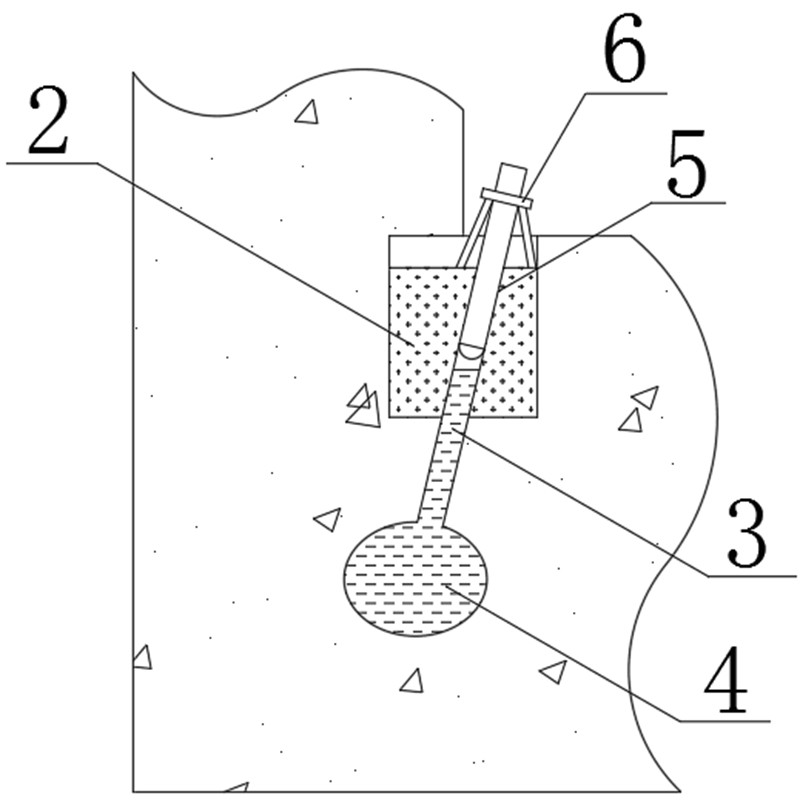
[0032] like Figure 1-5 As shown, a method for supporting surrounding rock of soft rock roadway under high impact geocompressive stress includes the following steps:
[0033] A: After the excavated deep roadway (1) needs to do complete and reliable first-level support, at a distance of about 5m from the head, the two bottom corners of the soft rock roadway (1) are excavated not less than 600mm×600mm The pressure relief groove (2), the depth of the pressure relief groove (2) is not less than 300mm, and the blast hole (3) of the vibration gun is arranged in the pressure relief groove (2). According to the difference in the strength of the surrounding rock, the blast hole (3) The eye distance is 800mm to 1200mm, the vertical angle of the drilling hole (3) is 5° to 25°, the horizontal angle is 0°, and the depth of the hole (3) is preferably 1800mm to 2200mm. The charge of the gun is 200-300 grams. After the gun is loaded, the hole (3) is sealed, and the total length of the hole s...
Embodiment 2
[0041] like Figure 1-5 As shown, a method for supporting surrounding rock of soft rock roadway under high impact geocompressive stress includes the following steps:
[0042] A: After the excavated deep roadway (1) needs to do complete and reliable first-level support, at a distance of about 5m from the head, the two bottom corners of the soft rock roadway (1) are excavated not less than 600mm×600mm The pressure relief groove (2), the depth of the pressure relief groove (2) is not less than 300mm, and the blast hole (3) of the vibration gun is arranged in the pressure relief groove (2). According to the difference in the strength of the surrounding rock, the blast hole (3) The eye distance is 800mm to 1200mm, the vertical angle of the drilling hole (3) is 5° to 25°, the horizontal angle is 0°, and the depth of the hole (3) is preferably 1800mm to 2200mm. The charging capacity of the gun is 200-300 grams. After the gun is loaded, the hole (3) is sealed. The total length of the...
PUM
 Abstract
Description
Claims
Application Information
 - R&D
- Intellectual Property
- Life Sciences
- Materials
- Tech Scout
- Unparalleled Data Quality
- Higher Quality Content
- 60% Fewer Hallucinations
Browse by: Latest US Patents, China's latest patents, Technical Efficacy Thesaurus, Application Domain, Technology Topic, Popular Technical Reports.
© 2025 PatSnap. All rights reserved.Legal|Privacy policy|Modern Slavery Act Transparency Statement|Sitemap|About US| Contact US: help@patsnap.com


