Roundness detection device

A detection device and roundness technology, applied in the direction of measuring devices, instruments, etc., can solve problems such as single detection form, difficulty in detecting roundness, errors, etc., and achieve the effect of simple structure of parts, high level of automation, and great promotion value

Pending Publication Date: 2021-11-05
SINOPEC OILFIELD EQUIP CORP
View PDF1 Cites 0 Cited by
  • Summary
  • Abstract
  • Description
  • Claims
  • Application Information

AI Technical Summary

Problems solved by technology

[0004] The invention provides a roundness detection device, which solves the problem that when a steel pipe is placed on a roller or a supporting structure, the roundness detection device can be disassembled after a section without being blocked by the roller or the supporting structure, and after bypassing the obstacle Installed on the steel pipe, resulting in waste of unnecessary man-hours, time-consuming and labor-intensive, and the problem that assembly line detection cannot be realized
[0005] The invention provides a roundness detection device, which solves the problem that it can only detect steel pipes of the same diameter, but is not suitable for detecting steel pipes with different diameters, and the detection form is single. Point detection, it is difficult to detect the roundness of all positions at the diameter, and it is easy to cause error problems

Method used


Image

  • Roundness detection device
  • Roundness detection device
  • Roundness detection device

Examples


Embodiment 1

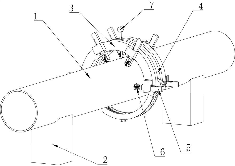
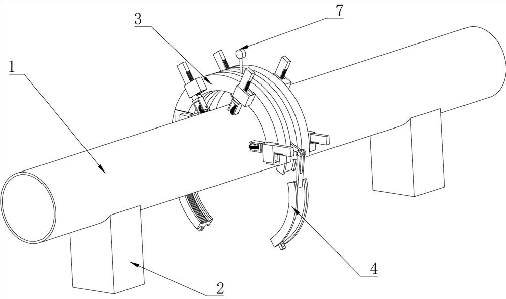
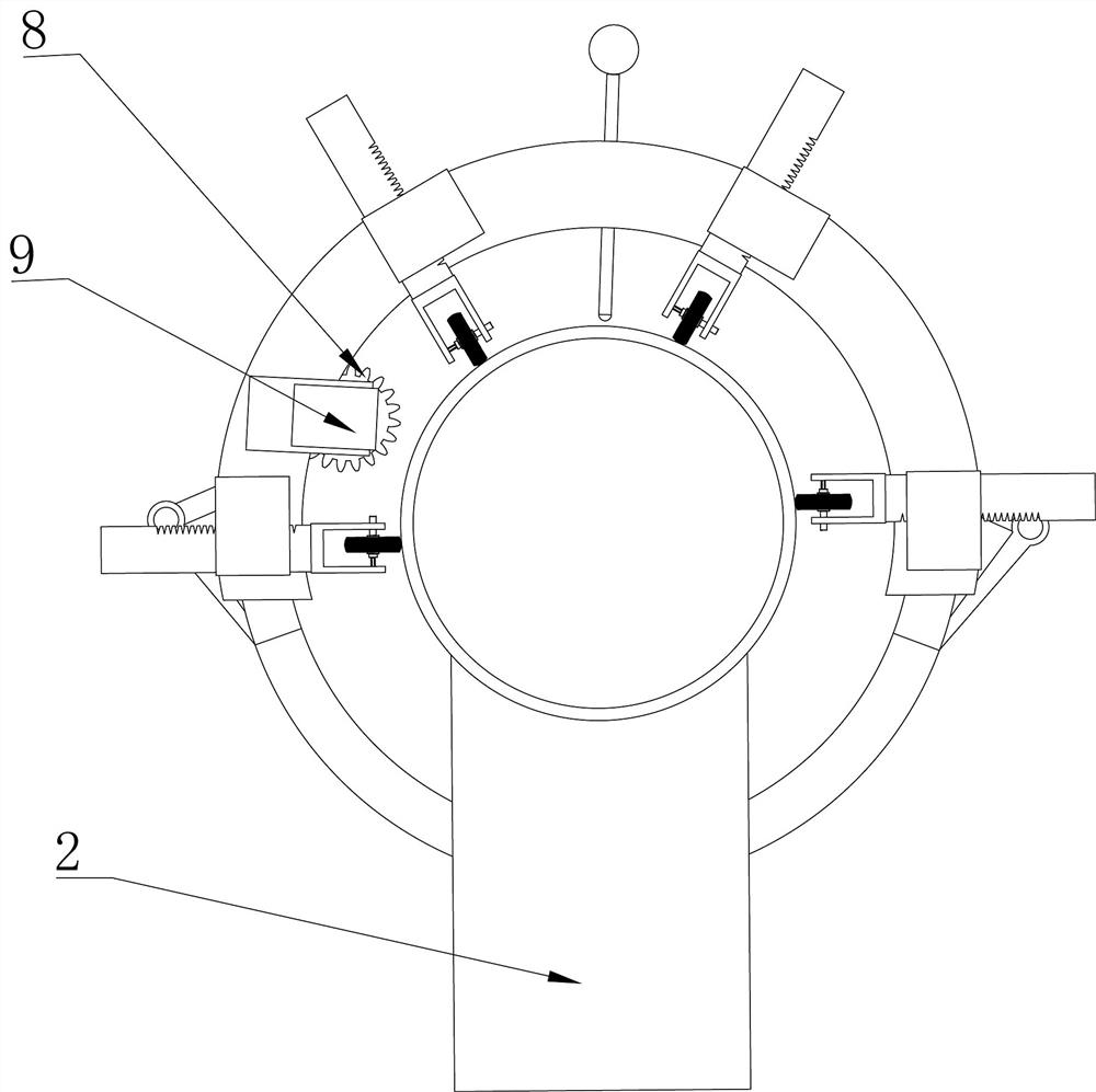
[0031] Such as Figure 1-7 Among them, a roundness detection device, a steel pipe 1 is supported on a bracket 2, which is characterized in that it includes two fan-shaped clamping devices 3 installed on the steel pipe 1, and multiple pointing clamping devices 3 are arranged on the clamping device 3 The telescopic rod 5 in the center of the circle is provided with a rotating device 4 that can be opened and closed between the two clamping devices 3. The rotating device 4 is slidably connected with the two clamping devices 3. Roundness table 7 for up and down adjustment;

[0032] Simultaneously drive a plurality of telescopic rods 5 to expand and contract, so that the center of the clamping device 3 coincides with the center of the steel pipe 1, adjust the roundness gauge 7, make the roundness gauge 7 lean against the steel pipe 1, and drive the rotating device 4 relative to the clamping device 3 Rotate so that the roundness meter 7 measures the roundness of the surface of the s...


PUM


Abstract

The invention provides a roundness detection device. A steel pipe is supported on a support. The roundness detection device is characterized in that: the roundness detection device comprises two fan-shaped clamping devices installed on the steel pipe; each clamping device is provided with a plurality of telescopic rods pointing to the circle center of the clamping device; a rotating device capable of being opened and closed is arranged between the two clamping devices; the rotating device is in sliding connection with the two clamping devices; a roundness meter capable of being adjusted up and down in the section circle center direction of the steel pipe is arranged on the rotating device; the telescopic rods are driven to stretch out and draw back at the same time, the circle centers of the clamping devices are made to coincide with the circle center of the steel pipe, the roundness meter is adjusted, the roundness meter is made to abut against the steel pipe, the rotating device isdriven to rotate relative to the clamping devices, and the roundness meter is made to measure the surface roundness of the steel pipe. Through the opening and closing of the detection device, waste of unnecessary working hours caused by dismounting and mounting of the device due to blocking of a roller or a supporting framework is avoided, the time of workers is saved, and assembly line detection can be achieved. The clamping devices drive the multiple telescopic rods to stretch out and draw back at the same time, and diameter roundness detection of different steel pipes can be achieved.

Description

technical field [0001] The invention relates to the field of steel pipe detection, in particular to a roundness detection device. Background technique [0002] In the actual steel pipe production industry, it is often necessary to detect the roundness of the steel pipe. The roundness measurement methods in the prior art include the rotary axis method, the three-point method, the two-point method, the projection method, and the coordinate method. The diameter of the steel pipe is generally relatively small. It is large and heavy, and vernier calipers cannot be used to measure directly. Using the other roundness measurement methods mentioned above requires handling steel pipes and moving the steel pipes to corresponding testing equipment, which takes a lot of time and labor costs, resulting in low testing efficiency and increased It takes a lot of man-hours and is not suitable for the assembly line inspection of large steel pipes. At the same time, when large steel pipes are ...

Claims


Application Information

Patent Timeline
IPC IPC(8): G01B21/20
CPCG01B21/20
Inventor 崔晓峰石弘彭新星张新芳罗红福蔡绪明周海波邓新林马有军彭元超蔡小青陈曦
Owner SINOPEC OILFIELD EQUIP CORP
Why Eureka
Try Eureka