
Dimming circuit, PCB and dimming power supply

A technology of dimming circuit and dimming port, which is applied to electrical components and other directions, can solve the problems of slow optocoupler switching speed, poor optocoupler current transfer ratio, and reduce signal transmission accuracy, so as to improve stability and improve signal transmission accuracy. , to achieve the effect of safe isolation

Pending Publication Date: 2021-11-05
佛山市雅昕电子有限公司
View PDF0 Cites 0 Cited by
  • Summary
  • Abstract
  • Description
  • Claims
  • Application Information

AI Technical Summary

Problems solved by technology

[0003] For the 0-10V dimming power supply on the market, its dimming port needs to be isolated from the main circuit. The optocoupler is used as an intermediate device in the existing market to realize the isolation between the dimming part and the main circuit. The PWM signal is input at the light receiving end, and the same PWM signal is output at the light receiving end or converted into an analog signal to control the output current; but in the working process of the dimming power supply, due to the slow switching speed of the optocoupler, there is There is a large delay between them, which reduces the transmission accuracy of the signal, and the optocoupler is easily affected by the external temperature. The signal received by the terminal is normal, which reduces the stability of the dimming power supply

Method used


Image

  • Dimming circuit, PCB and dimming power supply
  • Dimming circuit, PCB and dimming power supply
  • Dimming circuit, PCB and dimming power supply

Examples


Embodiment Construction

[0024] The present invention provides a dimming circuit, a PCB board and a dimming power supply. In order to make the purpose, technical solution and effect of the present invention clearer and clearer, the present invention will be further described in detail below with reference to the accompanying drawings and examples.

[0025] In the description of the present invention, it should be understood that the terms "installation", "connection", etc. should be understood in a broad sense, and those of ordinary skill in the art can understand the specific meanings of the above terms in the present invention according to specific situations .

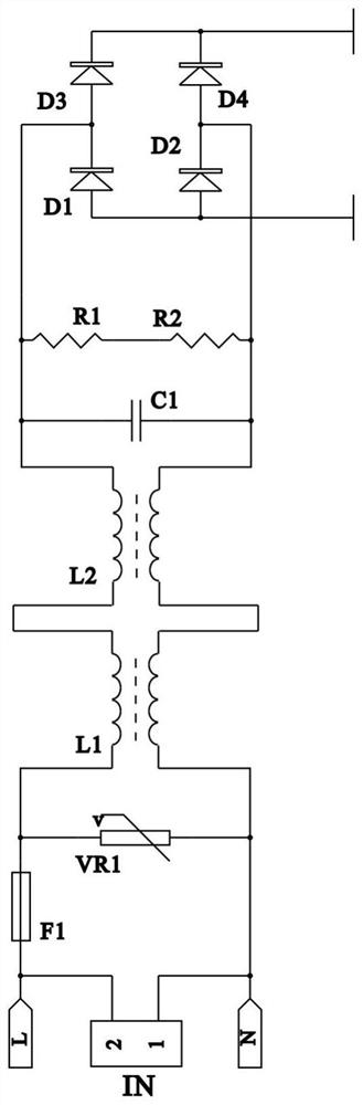
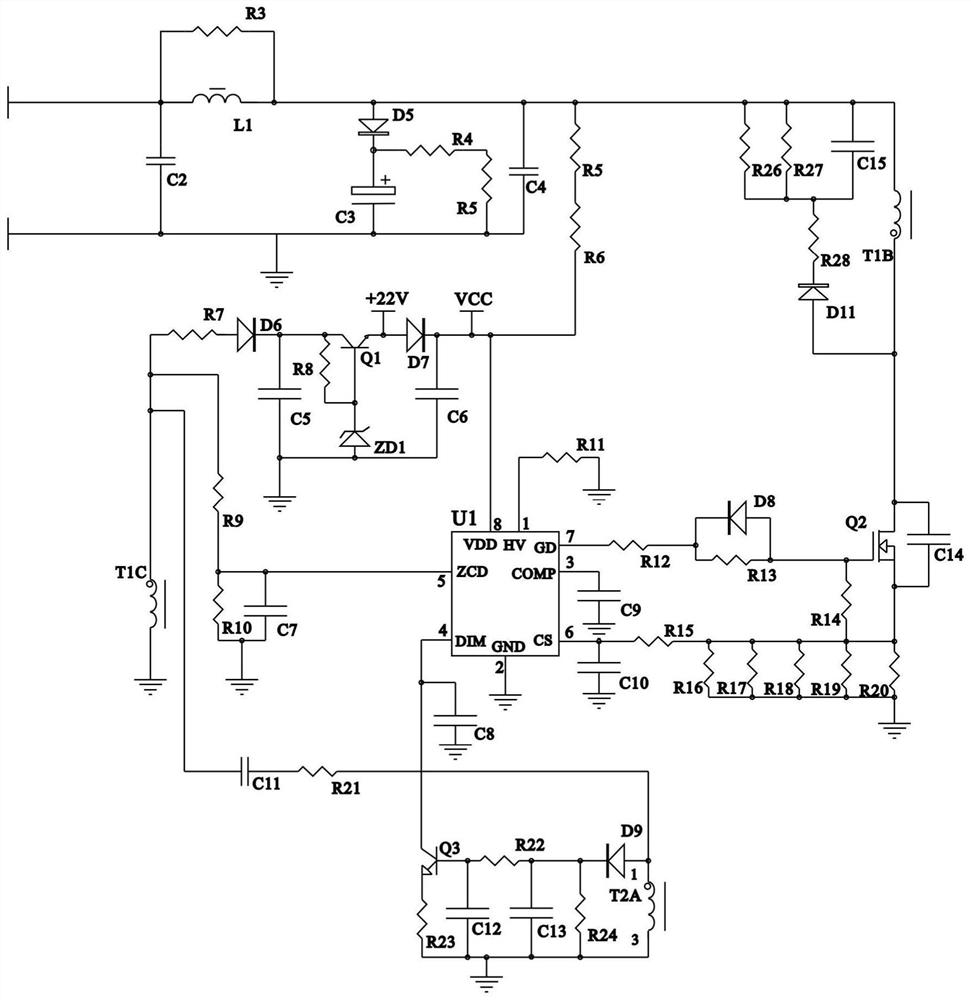
[0026] see Figure 1 to Figure 5 , the present invention provides a dimming circuit, comprising a dimming port, an input processing unit, a control unit, a dimming unit and an output processing unit, the input processing unit is used for filtering and rectifying the input AC power, the input The output end of the processing unit is connect...


PUM


Abstract

The invention discloses a dimming circuit, a PCB and a dimming power supply. The dimming circuit comprises a dimming port, an input processing unit, a control unit, a dimming unit and an output processing unit, wherein an output end of the input processing unit is connected with an input end of the control unit; the control unit comprises a primary coil T2A of a second transformer, the dimming unit comprises a secondary coil T2B of the second transformer; the secondary coil T2B of the second transformer is connected with a dimming port, and the primary coil T2A of the second transformer is in induction connection with the secondary coil T2B of the second transformer; an output end of the control unit is connected with an input end of the output processing unit, and the control unit is used for adjusting output current according to a dimming signal; according to the dimming circuit disclosed by the invention, the dimming signal inputted by the dimming port is safely isolated by adopting the second transformer, and optocoupler isolation in the prior art is replaced, so signal transmission precision can be improved.

Description

technical field [0001] The invention relates to the technical field of dimming control circuits, in particular to a dimming circuit, a PCB board and a dimming power supply. Background technique [0002] An optocoupler is also called a photoelectric isolator or a photocoupler. It uses light as a medium to transmit electrical signals. Usually, the emitter and the light receiver are packaged in the same tube. When the input signal is powered, the emitter After emitting light, the photoreceptor generates photocurrent and flows out from the output end after receiving the light, thus realizing the conversion of "electricity-optical-electricity"; the optocoupler has the advantages of small size, long life, no contact, strong anti-interference ability, output and The advantages of insulation between inputs and one-way transmission of signals have been widely used in digital circuits. [0003] For the 0-10V dimming power supply on the market, its dimming port needs to be isolated fr...

Claims


Application Information

Patent Timeline
IPC IPC(8): H05B47/10
CPCH05B47/10
Inventor 任茂涛万彩
Owner 佛山市雅昕电子有限公司
Learn More