A weight balancing gantry

A technology of weight balance and gantry, applied in the direction of workbench, crane, portable lifting device, etc., can solve the problems of cable blocking, high roof height and radial arm height

Pending Publication Date: 2021-11-05
克莱姆库什埃利
View PDF7 Cites 1 Cited by
  • Summary
  • Abstract
  • Description
  • Claims
  • Application Information

AI Technical Summary

Problems solved by technology

[0005] However, for example, when welding inside a vehicle's beaverpanel (the part of the trunk lid and under the trunk floor), the cables may be blocked by the trunk lid
Also, the vehicle's roof height may be too high for the radial arm

Method used


Image

  • A weight balancing gantry
  • A weight balancing gantry
  • A weight balancing gantry

Examples


Embodiment Construction

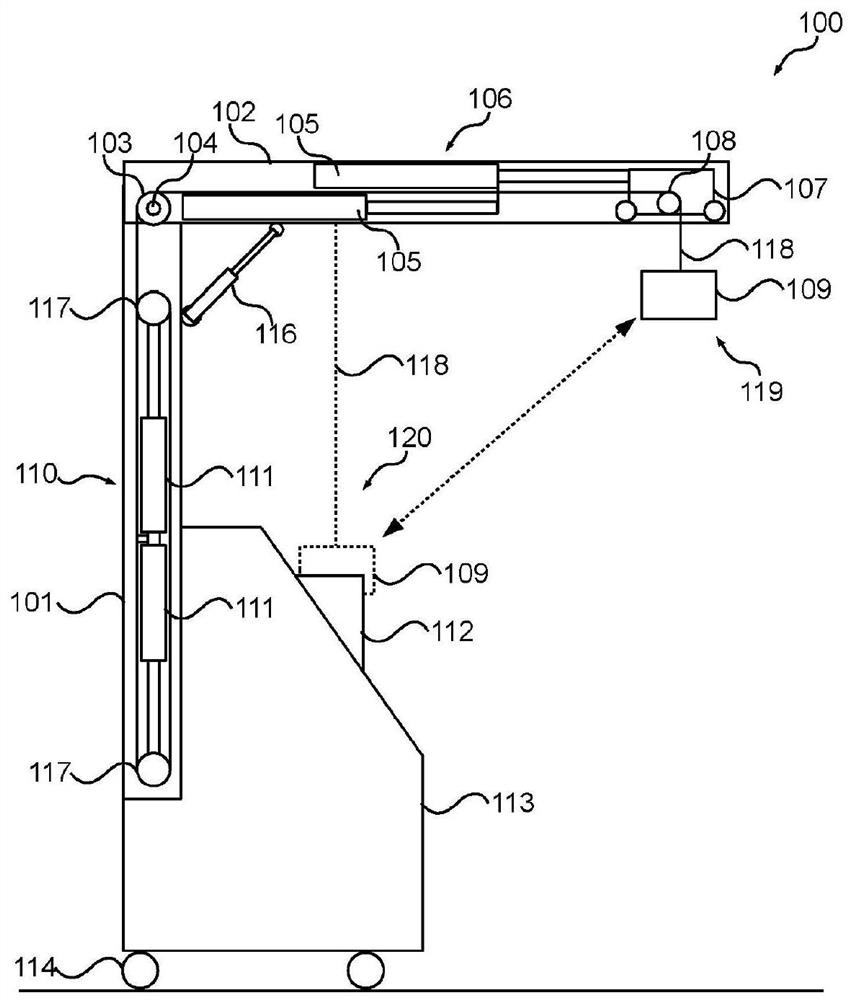
[0025] The weight balance stand 100 includes a tower 101 having a radial arm 102 pivotally coupled from a pivot point 104 at an upper end of the tower 101 for supporting an industrial tool 109 such as a point welding gun, etc.).

[0026] The stand 101 may be supported by an industrial cart 113 (such as a mobile spot welder, etc.) having casters 114 .

[0027] A corner brace 116 acts between the tower 101 and the radial arm 102 across the pivot point 104 .

[0028] In an embodiment, the radial arm 102 can further swing from side to side.

[0029] The stand 100 includes a weight balance mechanism 110 that may include counterweight balance pulleys 117 . Each pulley 117 may be pneumatically biased from a respective pneumatic cylinder 111, preferably in figure 1 The in-line manner shown in , to reduce the overall width of the tower 101 . In the illustrated embodiment, the weight balance mechanism 110 is concealed within the tower 101 .

[0030] In an embodiment, the balance me...


PUM


Abstract

A weight balancing gantry has a tower having a fixed length radial arm pivotally coupled from a pivot point at an upper end of the tower. An angle strut acts between the tower and the radial arm across the pivot point. A pivot point pulley is located at the upper end of the tower and a weight balancing mechanism located at the tower. A bogey runs along the radial arm and has a bogey pulley. A positioning mechanism at the radial arm has at least one controlled cylinder for positioning and holding the bogey along to the radial arm. A cable runs from the weight balancing mechanism, up across the pivot point pulley and over the bogey pulley to attach to an industrial tool.

Description

technical field [0001] The present invention generally relates to a weight balancing stand for balancing industrial tools such as spot welding guns and the like. Background technique [0002] Weight balancing stands are used in industry to vertically balance the weight of industrial tools such as spot welding guns in the auto repair industry. The weight of these tools can range from 10kg-25kg depending on the arm size used, making them bulky and difficult to use without the aid of a weight to balance the bench. [0003] US 2176979 A (Platz) of 24 October 1939 discloses a typical weight-balanced stand arrangement comprising horizontal radial arms supported by a tower. The carriage runs along horizontal radial arms and has on it a pneumatic balancing mechanism from which the spot welding gun is vertically balanced by cables. [0004] US 6087611 A (De Bruyn et al.) discloses a system for vertically balancing welding tongs comprising a spring balance attached from a horizontal...

Claims


Application Information

Patent Timeline
Patent Type & Authority Applications(China)
IPC IPC(8): B23K37/02B23Q1/25B25H1/10
CPCB23Q1/0054B25H1/0028B23Q1/25B23K37/02B66D3/04B23K37/0235B23K37/0282B23K37/0294B23K11/318B23K11/11B23Q11/001B66C23/48B66C23/72
Inventor 克莱姆·库什埃利
Owner 克莱姆库什埃利
Why Eureka
Try Eureka