Fusing machine for steel wire rope production and processing

A fuse machine and wire rope technology, which is applied in metal processing, dispersed particle separation, chemical instruments and methods, etc., can solve the problems of reduced safety performance, staff injury in peripheral operations, and low use value of fuse machines, so as to improve the fuse effect , Avoid contact deformation, improve the effect of cooling and shaping

Active Publication Date: 2021-11-09
江苏中英钢绳有限公司
View PDF10 Cites 0 Cited by
  • Summary
  • Abstract
  • Description
  • Claims
  • Application Information

AI Technical Summary

Problems solved by technology

[0003] During the production and processing of the existing steel wire rope, it is generally cut by a fuse machine. In order to prevent the bifurcation of the cut point, the cut point is usually processed into a tapered head by a fuse machine, so that it can be well prevented. The cutting point is bifurcated, but after the wire rope is cut off by the fuse machine, when it is transported out of the fuse machine, the temperature of the cut point is high and it is in a semi-hot melting state. When it is transported, it is easy to be damaged by external wind or other Factors lead to deformation of the cut-off point, and even multiple steel wires bifurcate again due to the semi-hot melting state, resulting in low use value of the fuse machine. At the same time, the high temperature of the cut-off point is easy to affect the surrounding staff cause injury and reduce its safety performance

Method used


Image

  • Fusing machine for steel wire rope production and processing
  • Fusing machine for steel wire rope production and processing
  • Fusing machine for steel wire rope production and processing

Examples


Embodiment Construction

[0031] The following will clearly and completely describe the technical solutions in the embodiments of the present invention with reference to the accompanying drawings in the embodiments of the present invention. Obviously, the described embodiments are only some, not all, embodiments of the present invention.

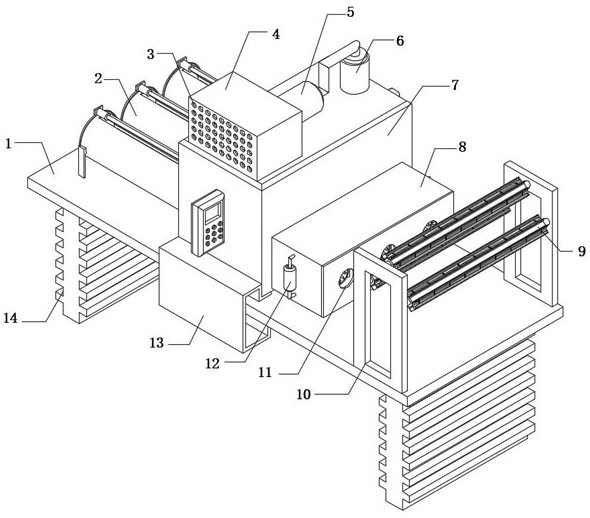
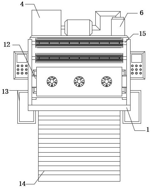
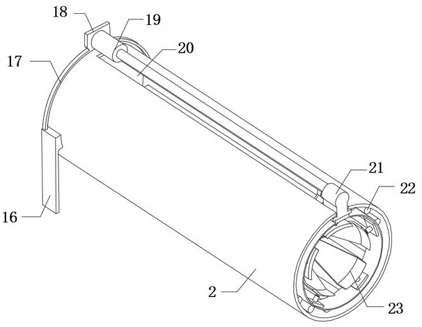
[0032] refer to Figure 1-4, a fuse machine for wire rope production and processing, including a processing table 1 and a fuse body 7, the top outer wall of the processing table 1 is fixedly connected with mounting plates 16 equidistantly, and every two adjacent mounting plates 16 are opposite to each other The side outer wall is fixedly connected with the same ring frame 17, the outer wall of the ring frame 17 is fixedly connected with the cooling tube 2, the outer wall of the cooling tube 2 above is provided with a sliding groove 20, and the inner wall of the sliding groove 20 is slidingly connected with a sliding block 21, the ring The top outer wall of frame 17 i...


PUM


Abstract

The invention belongs to the technical field of steel wire rope processing, and particularly relates to a fusing machine for steel wire rope production and processing. The fusing machine for steel wire rope production and processing comprises a processing table and a fusing machine body; mounting plates are fixedly connected to the outer wall of the top of the processing table at equal intervals; one annular frame is fixedly connected to the outer walls of the opposite sides of every two adjacent mounting plates; a cooling cylinder is fixedly connected to the outer wall of the annular frame; and a sliding groove is formed in the outer wall, located at the upper part, of the cooling cylinder. According to the fusing machine for steel wire rope production and processing, through the arrangement of a preheating box, an electromagnetic heater, an arc-shaped limiting plate and a heat conduction rod, before entering the fusing machine, the steel wire rope firstly penetrates through thep reheating box; the electromagnetic heater is started; the heat conduction rod transmits heat to the arc-shaped limiting plate; an inner abutting heat conduction frame in the arc-shaped limiting plate transmits the heat to the steel wire rope to perform preliminary preheating treatment on the steel wire rope; and therefore, it is guaranteed that the whole steel wire rope is in an easily-cut-off state when the steel wire rope is cut off in the fusing machine, and the fusing effect of a fusing point is improved.

Description

technical field [0001] The invention relates to the technical field of steel wire rope processing, in particular to a fuse machine for production and processing of steel wire ropes. Background technique [0002] The steel wire rope is a spiral steel wire bundle twisted together with steel wires whose mechanical properties and geometric dimensions meet the requirements according to certain rules. The steel wire rope is composed of steel wire, rope core and lubricating grease. The steel wire rope is first twisted into strands by multi-layer steel wires, and then twisted into a helical rope by a certain number of strands with the rope core as the center. In material handling machinery, it is used for lifting, pulling, tensioning and carrying. The steel wire rope has high strength, light weight, stable operation, and is not easy to break suddenly, and the operation is reliable. [0003] During the production and processing of the existing steel wire rope, it is generally cut b...

Claims


Application Information

Patent Timeline
IPC IPC(8): B21F11/00B21F23/00B23P25/00B01D53/00
CPCB21F11/00B21F23/00B23P25/00B01D53/00
Inventor 徐水英
Owner 江苏中英钢绳有限公司
Why Eureka
Try Eureka