Electronic rear lock and control method thereof

An electronic and lock cylinder technology, applied in the field of locks, can solve the problems of high cost, complicated electric unlocking or locking control, etc., and achieve the effects of low cost, easy control and simple control.

Pending Publication Date: 2021-11-09
SHENZHEN MAIHANDE IND
View PDF0 Cites 0 Cited by
  • Summary
  • Abstract
  • Description
  • Claims
  • Application Information

AI Technical Summary

Problems solved by technology

Usually, in order to reduce costs, users tend to choose to renovate old locks. Electronic door locks need to be compatible with fully automatic mode and manual mode of old locks. In related technologies, electronic door locks usually need to be equipped with more sensors, and the cost Higher, and the control of electric unlocking or locking is more complicated

Method used


Image

  • Electronic rear lock and control method thereof
  • Electronic rear lock and control method thereof
  • Electronic rear lock and control method thereof

Examples


Embodiment 1

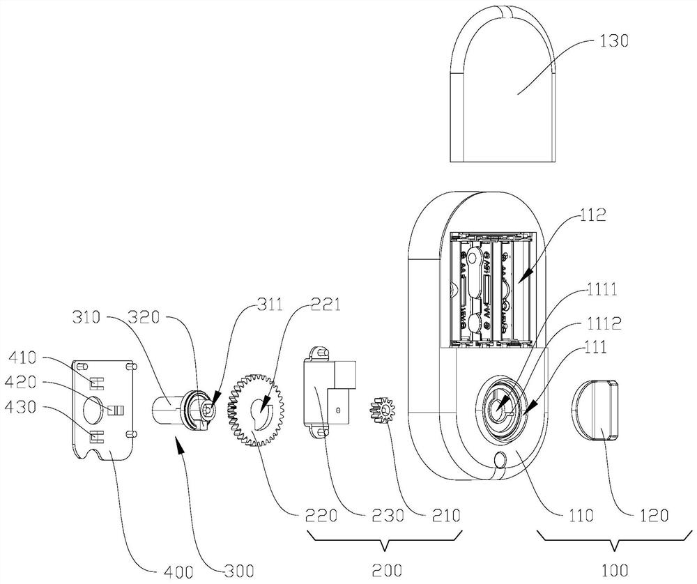
[0081] In this embodiment, the upper part is the first sensor 410 and the lower part is the third sensor 430 .

[0082] Unlock action:

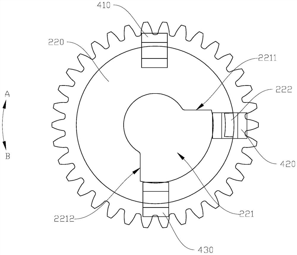
[0083] The lock cylinder is in the locked state, the convex rib 320 is abutted against the first abutting surface 2211, and the detection piece 222 is located at the second sensor 420;

[0084] The driving member 230 receives the unlock signal and drives the driving gear 210 to drive the driven gear 220 to rotate in the first direction A;

[0085] When the detection piece 222 reaches the third sensor 430, the lock cylinder is in the unlocked state, and the driving member 230 receives the first reset signal and drives the driving gear 210 to drive the driven gear 220 to rotate in the opposite direction of the first direction A;

[0086] When the detection piece 222 reaches the second sensor 420 , the driving member 230 receives the first completion signal and stops the action, the convex rib 320 abuts against the second abutting surface 2212 ...

Embodiment 2

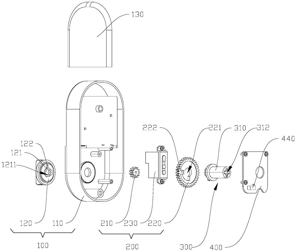
[0095] In this embodiment, the upper part is the third sensor 430 and the lower part is the first sensor 410 .

[0096] Unlock action:

[0097] The lock cylinder is in the locked state, the convex rib 320 abuts against the second abutting surface 2212 , and the detection piece 222 is located at the second sensor 420 .

[0098] The driving member 230 receives the unlock signal and drives the driving gear 210 to drive the driven gear 220 to rotate in the second direction B;

[0099] When the detection piece 222 reaches the first sensor 410, the lock cylinder is in the unlocked state, and the driving member 230 receives the third reset signal and drives the driving gear 210 to drive the driven gear 220 to rotate in the opposite direction of the second direction B;

[0100] When the detection piece 222 reaches the second sensor 420 , the driving member 230 receives the third completion signal and stops the action, the convex rib 320 abuts against the first abutting surface 2211 ,...


PUM


Abstract

The invention discloses an electronic rear lock and a control method thereof. The electronic rear lock comprises a shell, a driving assembly, a shaft sleeve and a base plate, wherein a sliding groove is formed in a driven gear, a protruding rib of the shaft sleeve is contained in the sliding groove, and the protruding rib can abut against a first abutting face or a second abutting face which are oppositely arranged through rotation of the driven gear, and therefore, electric unlocking and locking can be achieved in the mode that a driving piece drives the driven gear to drive the shaft sleeve to rotate, and manual unlocking and locking can also be achieved in the mode that the shaft sleeve is manually rotated to rotate in the sliding groove under the condition that the driven gear is not moved; three sensors are arranged on the base plate, the rotating position of the driven gear can be indicated, the three sensors can indicate the unlocking position, the initial position and the locking position respectively, the state of a lock cylinder can be recognized without arranging too many sensors, and control logic is simple.

Description

technical field [0001] The invention relates to the technical field of locks, in particular to an electronic rear lock and a control method thereof. Background technique [0002] With the improvement of living standards, the penetration rate of electronic door locks is gradually increasing. Usually, in order to reduce costs, users tend to choose to renovate old locks. Electronic door locks need to be compatible with fully automatic mode and manual mode of old locks. In related technologies, electronic door locks usually need to be equipped with more sensors, and the cost Higher, and the control of electric unlocking or locking is more complicated. Contents of the invention [0003] The present invention aims to solve at least one of the technical problems existing in the prior art. For this reason, the present invention proposes an electronic rear lock, which is compatible with a fully automatic mode and a manual mode, can reduce costs, and is relatively simple to contro...

Claims


Application Information

Patent Timeline
Patent Type & Authority Applications(China)
IPC IPC(8): E05B47/00
CPCE05B47/0001E05B2047/002E05B2047/0067E05B2047/0069
Inventor 李忠学吴育丽庞德志孔永宇
Owner SHENZHEN MAIHANDE IND
Why Eureka
Try Eureka