
New energy high-temperature-resistant cooling system for energy storage battery cabinet

An energy storage battery and cooling system technology, applied in the direction of secondary batteries, battery pack components, circuits, etc., can solve the problems of energy storage cabinet temperature imbalance, high cost of using air conditioners, and lower battery temperature, so as to reduce water resources Effects of waste, reduced floor space, and stable water storage

Inactive Publication Date: 2021-11-09
合肥召洋电子科技有限公司
View PDF9 Cites 0 Cited by
  • Summary
  • Abstract
  • Description
  • Claims
  • Application Information

AI Technical Summary

Problems solved by technology

[0002] With the rapid development of lithium battery technology, it is common for lithium-ion batteries to be used in megawatt (MW) energy storage systems. The battery packs of these MW-level energy storage systems mostly use new battery packs. In the battery energy storage cabinet; in the process of using the traditional energy storage cabinet, the air conditioner is generally used to cool the inside of the energy storage cabinet, but in the traditional technology, the air conditioner is only installed at the head and tail ends of the energy storage cabinet. This kind of situation causes the temperature in the entire energy storage cabinet to be unbalanced, so that the temperature of some batteries cannot be lowered, thus posing safety hazards, and the cost of using air conditioners is high, and it is not energy-saving and environmentally friendly. Therefore, we propose an energy storage battery Cabinet new energy anti-high temperature cooling system

Method used


Image

  • New energy high-temperature-resistant cooling system for energy storage battery cabinet
  • New energy high-temperature-resistant cooling system for energy storage battery cabinet
  • New energy high-temperature-resistant cooling system for energy storage battery cabinet

Examples


Embodiment Construction

[0023] The following will clearly and completely describe the technical solutions in the embodiments of the present invention with reference to the accompanying drawings in the embodiments of the present invention. Obviously, the described embodiments are only some, not all, embodiments of the present invention. Based on the embodiments of the present invention, all other embodiments obtained by persons of ordinary skill in the art without making creative efforts belong to the protection scope of the present invention.

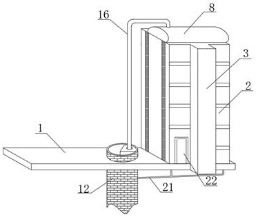
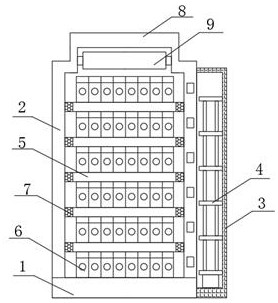
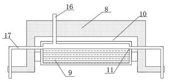
[0024] Such as Figure 1-5 As shown, a new energy high temperature resistant cooling system for energy storage battery cabinets, including a foundation 1, a vertical battery cabinet 2 is arranged on the foundation 1, a sealed chamber 3 is arranged on the front face of the vertical battery cabinet 2, and a ladder is installed in the sealed chamber 3 4. The interior of the vertical battery cabinet 2 is equidistantly provided with interlayer boards 5 , on which t...


PUM

PropertyMeasurementUnit
heightaaaaaaaaaa
depthaaaaaaaaaa

Abstract

The invention discloses a new energy high-temperature-resistant cooling system for an energy storage battery cabinet. The system comprises a foundation; a vertical battery cabinet is arranged on the foundation; a sealing cavity is formed in the front end face of the vertical battery cabinet; a crawling ladder is installed in the sealing cavity; partition plates are longitudinally arranged in the vertical battery cabinet at equal intervals; battery packs are placed on the partition plates, air holes are uniformly formed in the two ends of the partition plates; and an arc-shaped top base is arranged at the upper end of the vertical battery cabinet. According to the new energy high-temperature-resistant cooling system for an energy storage battery cabinet, a well is excavated, the battery cabinet is cooled through the low temperature of well water, the well water climbs and flows for a long distance through a coiled pipe group to take away heat of each layer of the battery cabinet, and therefore the heat dissipation effect is remarkably improved; and due to the U-shaped continuous design of the coiled pipe group, the flowing distance and the climbing difficulty are increased, and the flowing time of cooling water on the side is prolonged. The system is suitable for different working conditions, and brings a better use prospect.

Description

technical field [0001] The invention relates to the technical field of energy storage battery cabinets, in particular to a new energy high temperature resistant cooling system for energy storage battery cabinets. Background technique [0002] With the rapid development of lithium battery technology, it is common for lithium-ion batteries to be used in megawatt (MW) energy storage systems. The battery packs of these MW-level energy storage systems mostly use new battery packs. In the battery energy storage cabinet; in the process of using the traditional energy storage cabinet, the air conditioner is generally used to cool the inside of the energy storage cabinet, but in the traditional technology, the air conditioner is only installed at the head and tail ends of the energy storage cabinet. This situation causes the temperature in the entire energy storage cabinet to be unbalanced, so that the temperature of some batteries cannot be lowered, thereby posing safety hazards, an...

Claims


Application Information

Patent Timeline
Patent Type & Authority Applications(China)
IPC IPC(8): H01M10/613H01M10/627H01M10/6556H01M10/6568H01M10/6561H01M50/204H01M50/244H01M50/251H01M50/289H01M10/0525
CPCH01M10/613H01M10/627H01M10/6556H01M10/6568H01M10/6561H01M50/204H01M50/244H01M50/251H01M50/289H01M10/0525Y02E60/10
Inventor 周细文张立辉李辉
Owner 合肥召洋电子科技有限公司
Learn More