Solar collector

A technology of solar heat collectors and vacuum heat collecting tubes, applied in the field of solar heat collectors, can solve the problems of inconspicuous heating effect, short heat exchange time, fast liquid flow rate, etc.

Inactive Publication Date: 2015-04-01
WUHU BEST NEW ENERGY DEV
View PDF5 Cites 8 Cited by
  • Summary
  • Abstract
  • Description
  • Claims
  • Application Information

AI Technical Summary

Problems solved by technology

Most of the inner flow tubes of existing solar collectors are cylindrical, and the liquid flow rate inside them is fast, the heat exchange time is short, and the heating effect is not obvious

Method used


Image

  • Solar collector
  • Solar collector
  • Solar collector

Examples


Embodiment Construction

[0026] Specific embodiments of the present invention will be described in detail below in conjunction with the accompanying drawings. It should be understood that the specific embodiments described here are only used to illustrate and explain the present invention, and are not intended to limit the present invention.

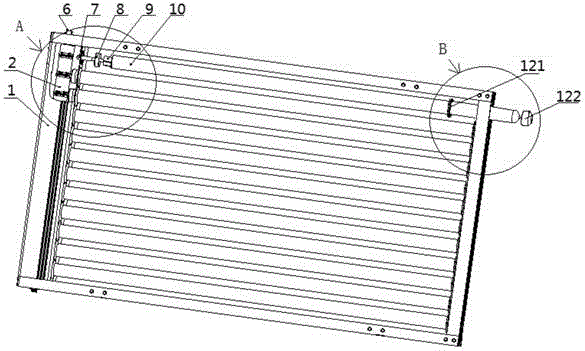
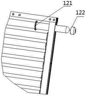
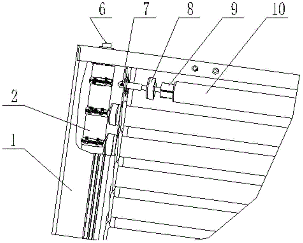
[0027] see figure 1 , the present invention provides a solar thermal collector, which comprises a frame body 1, an inner flow tube 2 located in one frame of the frame body 1, and a plurality of vacuum heat collecting tubes 10 located on the frame body 1, the vacuum The heat-collecting tube 10 is provided with a heat transfer medium and one end is connected to the inner flow pipe 2; the cross section of the inner flow pipe 2 perpendicular to the length direction is an elliptical plane, and the two ends of the inner flow pipe 2 are respectively equipped with Or the through hole 6 of water outlet.

[0028] Through the above technical scheme, the inner flow tube 2...


PUM


Abstract

The invention discloses a solar collector which comprises a frame (1), an inner flow tube (2) and a plurality of evacuated collector tubes (10), wherein the inner flow tube (2) is positioned in one edge frame of the frame (1), and the evacuated collector tubes (10) are positioned on the frame (1). Heat transfer media are arranged in the evacuated collector tubes (10), one end of each evacuated collector tube is connected with the inner flow tube (2), the cross section of the inner flow tube (2) perpendicular to the length direction is an elliptic plane, and through holes (6) are formed in two ends of the inner flow tube (2) respectively. The solar collector is rapid in heating, complete in energy transfer and better in heat collecting effect.

Description

technical field [0001] The invention relates to the field of solar energy equipment, in particular to a solar heat collector. Background technique [0002] A solar collector is a device used to receive sunlight and convert the received sunlight into heat for heating. Most of the inner flow pipes of existing solar heat collectors are cylindrical, and the liquid flow rate inside is relatively fast, the heat exchange time is short, and the heating effect is not obvious. Contents of the invention [0003] The object of the present invention is to provide a solar heat collector, which has fast heating, thorough energy transfer and better heat collection effect. [0004] In order to achieve the above object, the present invention provides a solar thermal collector, which includes a frame, an inner flow tube located in one frame of the frame, and a plurality of vacuum collectors located on the frame. Heat pipe, the vacuum heat collection tube is provided with a heat transfer me...

Claims


Application Information

Patent Timeline
Patent Type & Authority Applications(China)
IPC IPC(8): F24J2/05F24J2/24F24J2/46F24S10/40F24S10/70
CPCY02E10/44
Inventor 汪祥鹏
Owner WUHU BEST NEW ENERGY DEV
Why Eureka
Try Eureka