Oil cooling system and oil cooler

A technology of oil cooling system and oil cooler, which is applied in refrigerators, refrigeration components, heat exchanger shells, etc., and can solve problems such as increased noise of oil pumps and impact on oil pump life

Inactive Publication Date: 2015-09-09
GREE ELECTRIC APPLIANCES INC
View PDF7 Cites 7 Cited by
  • Summary
  • Abstract
  • Description
  • Claims
  • Application Information

AI Technical Summary

Problems solved by technology

When the oil pump is running, gas and oil enter the oil pump together, which not only greatly increases the noise of the oil pump, but also has a certain impact on the life of the oil pump

Method used


Image

  • Oil cooling system and oil cooler
  • Oil cooling system and oil cooler
  • Oil cooling system and oil cooler

Examples


Embodiment Construction

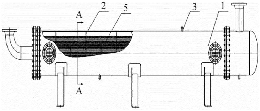
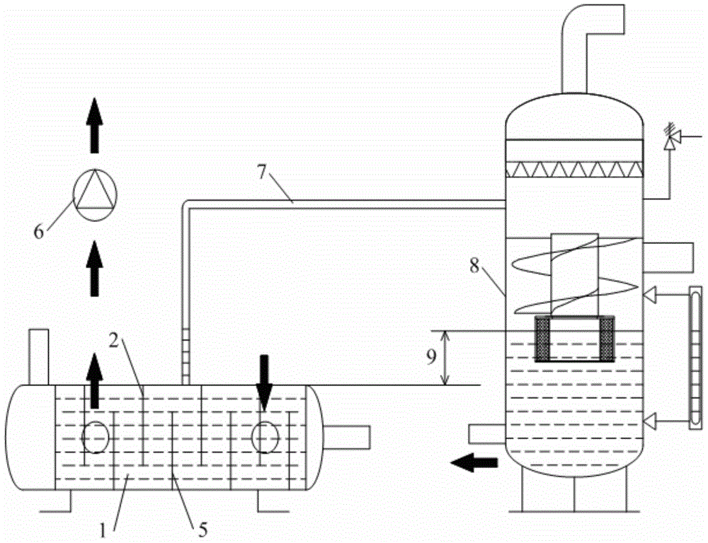
[0021] The invention discloses an oil cooler, which reduces the influence of refrigerant gas in the shell-and-tube oil cooler on the noise and performance of the oil pump in the oil cooling system; the invention also provides an oil cooling system.

[0022] The technical solutions in the embodiments of the present invention will be clearly and completely described below in conjunction with the accompanying drawings in the embodiments of the present invention. Obviously, the described embodiments are only some, not all, embodiments of the present invention. Based on the embodiments of the present invention, all other embodiments obtained by persons of ordinary skill in the art without making creative efforts fall within the protection scope of the present invention.

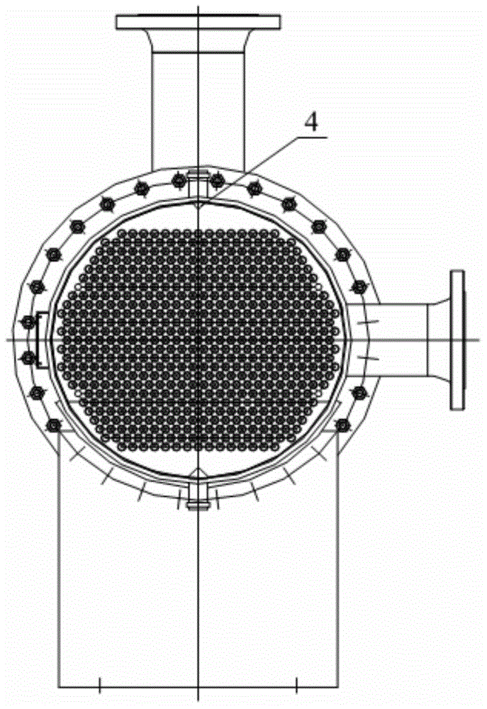
[0023] Such as figure 1 with figure 2 as shown, figure 1 Schematic diagram of the structure of the oil cooler provided by the present invention; figure 2 for figure 1 A cross-sectional view along the directi...


PUM


Abstract

The invention provides an oil cooler. The oil cooler comprises an oil cooler shell, and a baffle plate fixed in the oil cooler shell, wherein the baffle plate comprises an upper baffle plate connected with the upper part of the oil cooler shell, and a lower baffle plate connected with the lower part of the oil cooler shell; and a ventilating port penetrating through a thickness direction of the upper baffle plate is formed in the top of the upper baffle plate. As the ventilating port is formed in the top of the upper baffle plate, and a gas leading-out joint communicated with the top of the oil cooler is formed, when refrigerant gas is evaporated and generated in the oil cooler, the gas is leaded out by the gas leading-out joint through the ventilating port in the upper baffle plate to prevent steam from entering an oil pump along with cooled oil, so that the noise of the oil pump is lowered, and the service life of the oil pump is prolonged. The invention further provides an oil cooling system.

Description

technical field [0001] The invention relates to the technical field of refrigeration systems, and more specifically, to an oil cooling system and an oil cooler. Background technique [0002] In the refrigeration system, the existing shell-and-tube oil cooler only considers heat exchange, and does not consider that after the refrigerant and the refrigerating oil are miscible, they evaporate inside the oil cooler. The evaporated refrigerant exists on the top of the oil cooler and cannot be discharged, especially Large shell and tube oil cooler. [0003] At the same time, some refrigerating oils and refrigerants have a particularly strong mutual solubility. When the unit is running, due to the increase in the internal pressure of the oil cooler, more refrigerants dissolve into the refrigerating oil; Evaporates off, forms gas, accumulates at the top of the oil cooler. When the oil pump is running, gas and oil enter the oil pump together, which not only greatly increases the no...

Claims


Application Information

Patent Timeline
Patent Type & Authority Applications(China)
IPC IPC(8): F28F9/24F25B43/02
Inventor 安亚洲
Owner GREE ELECTRIC APPLIANCES INC
Why Eureka
Try Eureka