Anti-icing system and method for aero-engine intake support plate

A technology of aero-engines and anti-icing systems, which is applied in the direction of machines/engines, mechanical equipment, jet propulsion devices, etc., and can solve the problems of poor heat transfer effects of anti-icing systems

Inactive Publication Date: 2016-09-07
SHANGHAI JIAO TONG UNIV
View PDF6 Cites 7 Cited by
  • Summary
  • Abstract
  • Description
  • Claims
  • Application Information

AI Technical Summary

Problems solved by technology

[0006] The purpose of the present invention is to provide an anti-icing system and anti-icing method for the air intake s

Method used


Image

  • Anti-icing system and method for aero-engine intake support plate
  • Anti-icing system and method for aero-engine intake support plate

Examples


Embodiment Construction

[0021] The specific implementation manner of the present invention will be described in more detail below with reference to schematic diagrams. Advantages and features of the present invention will be apparent from the following description and claims. It should be noted that all the drawings are in a very simplified form and use imprecise scales, and are only used to facilitate and clearly assist the purpose of illustrating the embodiments of the present invention.

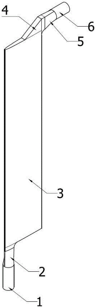
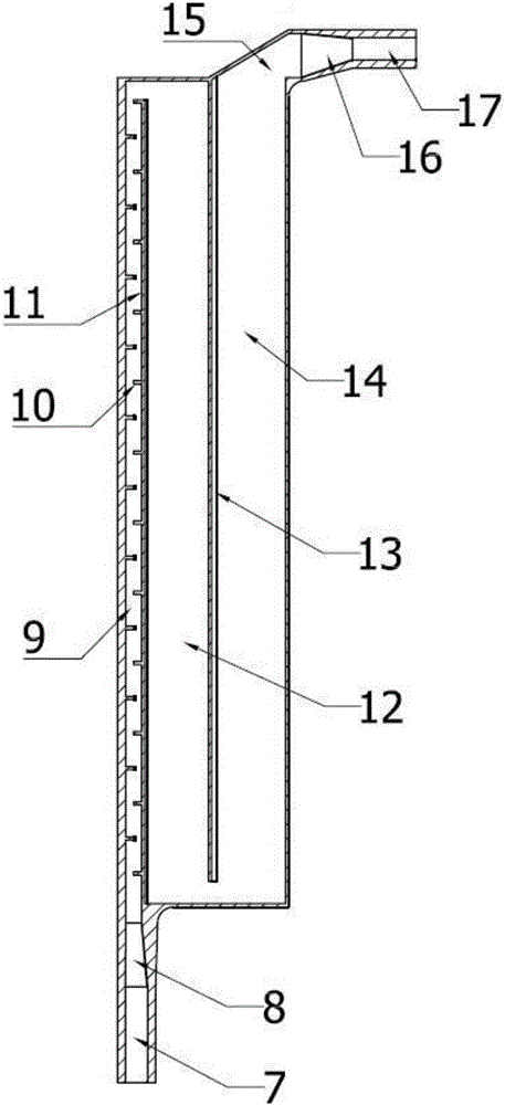
[0022] like Figure 1~2 As shown, this embodiment provides an anti-icing system for an air intake strut of an aero-engine, including an isolation unit and a heat medium delivery unit (not shown), the air intake strut has a cavity, and the cavity The cavity has an inlet end and an outlet end, the isolation unit is fixed in the cavity, and is used to divide the cavity into a plurality of interconnected channel cavities, and the heat medium transported by the heat medium delivery unit passes through the The inlet ...


PUM


Abstract

The invention provides an anti-icing system for an aero-engine intake support plate. The anti-icing system comprises an isolating unit and a thermal medium conveying unit. The intake support plate is provided with a cavity. The cavity is provided with an inlet end and an outlet end. The isolating unit is fixed into the cavity and used for dividing the cavity into multiple channel cavity bodies communicating with one another. A thermal medium conveyed by the thermal medium conveying unit enters the channel cavity bodies through the inlet end and is discharged from the outlet end. The anti-icing system comprises the channel cavity bodies communicating with one another, on the one hand, the flowing time of the thermal medium in the cavity is prolonged, and accordingly the heat exchange effect of the thermal medium and the intake support plate is increased; and on the other hand, relative to the integrated cavity structure, the division type structure with the channel cavity bodies has the acceleration effect on the thermal medium, the temperature of the intake support plate can be increased through the thermal medium of which the flowing speed is increased, and the heat exchange effect is further improved.

Description

technical field [0001] The invention relates to an anti-icing system of an aero-engine, in particular to an anti-icing system and an anti-icing method for an air intake support plate of an aero-engine. Background technique [0002] Aircraft icing is a serious problem that endangers flight safety, and flight accidents related to icing occur every year. The aviation gas turbine engine is the most sensitive part of the icing parts of the aircraft. Due to the high-speed rotation of the engine, the air in the intake port is in a suction state, the airflow accelerates, and the static temperature drops, making the air intake system of the aeroengine more vulnerable to icing weather. impact and are more prone to freezing. Once the engine intake system freezes, it will change the aerodynamic characteristics of the intake system, increase the flow resistance, make the intake air field unevenly distributed, and cause airflow distortion in light cases, thereby affecting the working sta...

Claims


Application Information

Patent Timeline
IPC IPC(8): F02C7/047
CPCF02C7/047
Inventor 雷桂林董威周建军闵现花
Owner SHANGHAI JIAO TONG UNIV
Why Eureka
Try Eureka