Household anti-falling power strip

An anti-dropping and plug-in technology, applied in the direction of preventing contact with live contacts, electrical components, coupling devices, etc., can solve the problems of easy loose plugs, damage to electrical components, small contact area of ​​shrapnel, etc., to avoid poor contact. , The effect of ensuring signal transmission and eliminating security risks

Inactive Publication Date: 2021-11-09
韩银城
View PDF0 Cites 1 Cited by
  • Summary
  • Abstract
  • Description
  • Claims
  • Application Information

AI Technical Summary

Problems solved by technology

[0003] However, the existing plug-in strips still have the following deficiencies in the actual use process: first, because they do not have the function of anti-loosening, after the connector plug is inserted into the jack, it cannot be well restrained, making the plug easy to Loose, if the plug is overheated, it will cause electrical safety hazards and electric shock, or a short circuit may cause fire hazards, and the loose plug can easily detach from the jack, resulting in sudden power failure, and it is easy to damage some electrical appliances in operation, such as refrigerators. , computers, etc., which can easily damage the electrical components and cause unnecessary economic losses, and in the long-term use process, it will cause poor contact and other situations, which will affect the use effect of the plug-in strip; In the process of inserting the plug-in strip, since the contact area between the teeth of the plug and the shrapnel inside the plug-in strip is small at the beginning, it is also easy to cause the danger of electric leakage and electric shock. security risks

Method used


Image

  • Household anti-falling power strip
  • Household anti-falling power strip
  • Household anti-falling power strip

Examples


Embodiment Construction

[0020] Next, the technical solutions in the embodiments of the present invention will be described in connection with the drawings of the embodiments of the present invention, and it is understood that the described embodiments are merely the embodiments of the present invention, not all of the embodiments. Based on the embodiments of the present invention, all other embodiments obtained by those of ordinary skill in the art are in the range of the present invention without making creative labor premise.

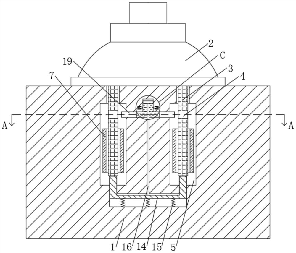
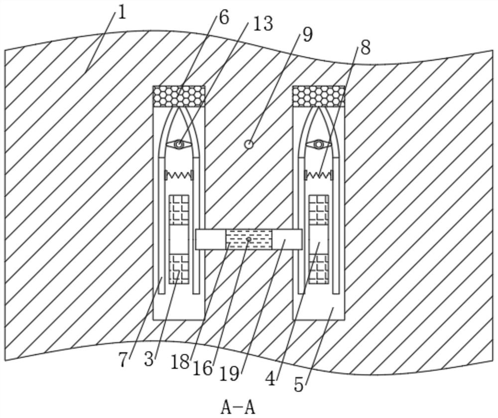
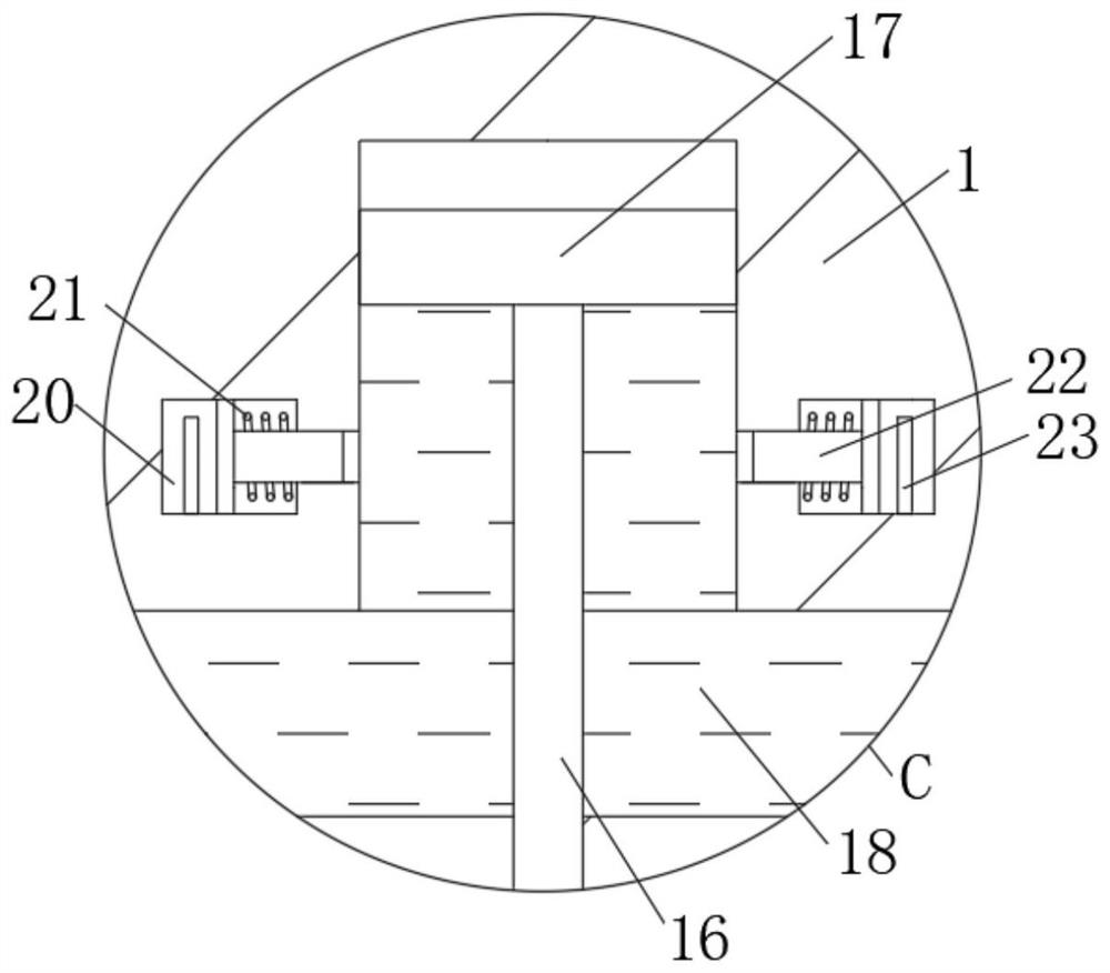
[0021] See Figure 1-6 A household anti-shedding socket, comprising a body inserted row, row insertion body 1 has an upper end plug socket activity 2, on both sides of the bottom plug 2 are fixedly connected with a shaper 3, the central gear 3 interposed defines a limiting holes 4, inside the body 1 of the inserted row defines two sets of 3-phase Shaper adapted cavity 5, the cavity 5 is fixed to one end electrically connected to a contact block 6, block an end of the electrical c...


PUM


Abstract

The invention relates to the technical field of electric connectors, and discloses a household anti-falling power strip, which comprises a power strip main body. The upper end of the power strip main body is movably sleeved with a plug, the two sides of the bottom of the plug are fixedly connected with insertion teeth, the middle parts of the insertion teeth are provided with limiting holes, and the interior of the power strip main body is provided with two groups of cavities matched with the insertion teeth. Through the arrangement of a reset spring, an elastic piece, a limiting block and a clamping block, after the insertion teeth are completely inserted, a cam can be deflected by rotating a rotating rod, so that the two sides of the elastic piece are inwards clamped under the tension effect of the reset spring, the elastic piece is tightly attached to the insertion teeth, the poor contact condition can be avoided, and the stability of signal transmission of the connector is ensured; meanwhile, the clamping blocks can be pressed by the hard rubber belt, so that the limiting blocks are always clamped in the limiting holes in the use process of the power strip in the working process of the power strip, the insertion teeth are prevented from loosening or even falling off in the use process, potential safety hazards are thoroughly eliminated, and damage to all electric appliances is prevented.

Description

Technical field [0001] Technical Field The present invention relates to an electrical connector, in particular a household-off preventing inserted row. Background technique [0002] Strip line socket with a number that is, also known as strip, wire lengthening assembly scientific name or extension cord socket. It refers to the number of inserted row with power cord and plug sockets and can be moved, can be connected to more than one plug, saving space and save the line. [0003] However, the existing row is inserted in actual use, there is also the following disadvantages: First, since there is no function of preventing loosening, so that the connector plug into the jack, no preferable constraints, such that the plug is easy loose, if the plug overheating can also cause electrical safety hazards of electric shock or short circuit caused a fire hazard and loose plug can easily out jack, resulting in a sudden power failure, it is easy to work some electrical appliances, such as ref...

Claims


Application Information

Patent Timeline
Patent Type & Authority Applications(China)
IPC IPC(8): H01R13/629H01R13/44H01R13/502
CPCH01R13/629H01R13/502H01R13/44
Inventor 韩银城
Owner 韩银城
Why Eureka
Try Eureka