
Fabricated beam-column connecting joint and construction method thereof

A beam-column connection and prefabricated technology, which is applied in the direction of architecture and building construction, can solve the problems of restricting the construction efficiency of prefabricated buildings, too long reserved steel bars for components, and difficult construction of beam-column joints, etc., and achieve the joint force transmission mechanism The effects of being direct and reliable, shortening the lap length, and simplifying the prefabricated construction process

Pending Publication Date: 2021-11-12
HUADONG BUILDING CO LTD OF CHINA CONSTR FIFTH ENG BUREAU +3
View PDF5 Cites 4 Cited by
  • Summary
  • Abstract
  • Description
  • Claims
  • Application Information

AI Technical Summary

Problems solved by technology

According to the requirements of the code, the bottom reinforcement of the prefabricated beam at the mid-span node of the prefabricated concrete frame structure must meet the larger value of LabE and hc / 2+5d, resulting in excessive reinforcement density in the core area of ​​the node, which is likely to cause the problem of reinforcement collision in the core area
The current mainstream connection forms of vertical components are sleeve grouting connection and grout-anchor lap connection. The construction of these two connection methods is cumbersome, and the lack of accurate detection methods greatly limits the construction efficiency of prefabricated buildings.
[0004] It can be seen that the conventional prefabricated joint connection has the disadvantages of too long reserved steel bars, high technical requirements, and complicated construction technology, especially in beam-column joints with high steel density.

Method used


Image

  • Fabricated beam-column connecting joint and construction method thereof
  • Fabricated beam-column connecting joint and construction method thereof

Examples


Embodiment Construction

[0032] In order to make the purpose, technical solutions and advantages of the embodiments of the present invention clearer, the technical solutions in the embodiments of the present invention will be clearly and completely described below in conjunction with the drawings in the embodiments of the present invention. Obviously, the described embodiments It is a part of embodiments of the present invention, but not all embodiments. The components of the embodiments of the invention generally described and illustrated in the figures herein may be arranged and designed in a variety of different configurations.

[0033] Accordingly, the following detailed description of the embodiments of the invention provided in the accompanying drawings is not intended to limit the scope of the claimed invention, but merely represents selected embodiments of the invention. Based on the embodiments of the present invention, all other embodiments obtained by persons of ordinary skill in the art wi...


PUM


Abstract

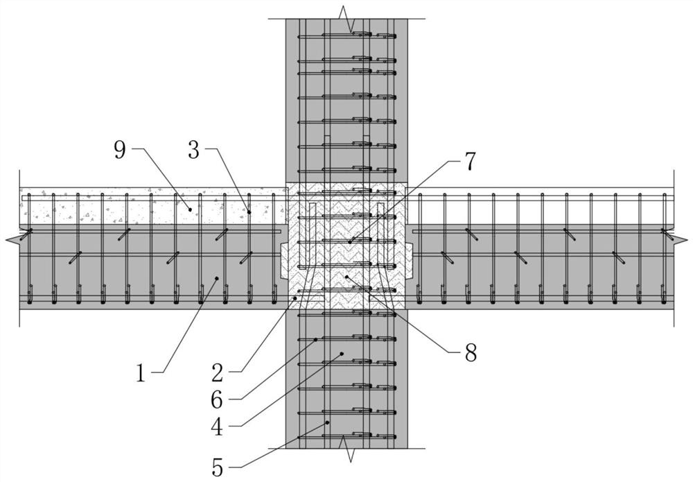
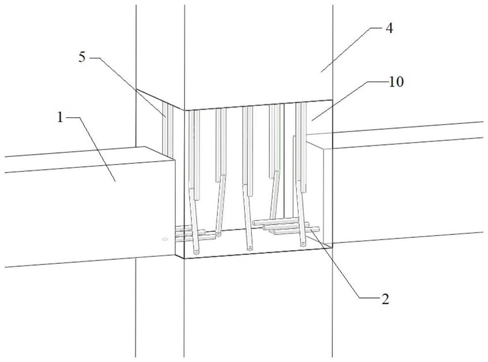
The invention relates to a fabricated beam-column connecting joint and a construction method. The connecting joint comprises a prefabricated beam and a prefabricated column, wherein a joint core area is formed at the joint of the prefabricated beam and the prefabricated column, column longitudinal bars are arranged on the prefabricated column, the column longitudinal bars of the adjacent prefabricated columns are in lap joint in the joint core area, the prefabricated column is arranged in the joint core area, and a high-strength material is poured in the joint core area to form a post-pouring core area. Compared with the prior art, the connecting joint has the advantages of direct and reliable force transmission, convenience in construction and the like.

Description

technical field [0001] The invention belongs to the technical field of prefabricated buildings, and specifically relates to a prefabricated beam-column connection node and a construction method thereof. Background technique [0002] At present, prefabricated concrete frame structures are widely used in the field of building structures, and the technology and regulations are relatively mature. Existing prefabricated buildings have also made great progress after years of development. [0003] Nodes bear and transmit various complex loads such as axial force, shear force, and bending moment from beams and columns, and are the key elements to ensure structural safety. According to the requirements of the code, the prefabricated beam bottom reinforcement of the mid-span mid-span node of the prefabricated concrete frame structure must meet the larger value of LabE and hc / 2+5d, resulting in excessive reinforcement density in the core area of ​​the node, which is likely to cause the...

Claims


Application Information

Patent Timeline
Patent Type & Authority Applications(China)
IPC IPC(8): E04B1/21
CPCE04B1/21
Inventor 王深山吴宏磊戴立军刘海东储居礼易溪熊明荣邱令乾王毅
Owner HUADONG BUILDING CO LTD OF CHINA CONSTR FIFTH ENG BUREAU
Learn More