
Optical driving assembly

A technology for driving components and optical components, applied in optical components, optics, instruments, etc., can solve the problems of limited anti-shake effect, high unit price, high power consumption, etc., to achieve the effect of optical anti-shake

Pending Publication Date: 2021-11-12
CHANGZHOU RAYTECH OPTRONICS CO LTD
View PDF0 Cites 0 Cited by
  • Summary
  • Abstract
  • Description
  • Claims
  • Application Information

AI Technical Summary

Problems solved by technology

However, this type of solution has disadvantages such as high power consumption, limited anti-shake effect, large product size and high unit price.

Method used


Image

  • Optical driving assembly
  • Optical driving assembly
  • Optical driving assembly

Examples


Embodiment Construction

[0029] The present invention will be further described below in conjunction with the accompanying drawings and embodiments.

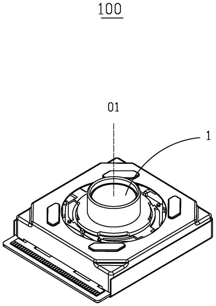
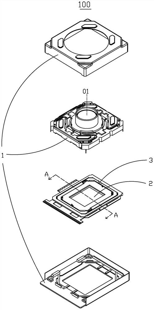
[0030] see Figure 1-Figure 10 , the embodiment of the present invention provides an optical driving assembly 100, including an optical element 1, an optical sensor 2 and a driving module 3. The optical element 1 has an optical axis 01, the optical sensor 2 and the optical element 1 are arranged along the optical axis 01, and the driving module 3 drives the optical sensor 2 to translate along a direction perpendicular to the optical axis 01.

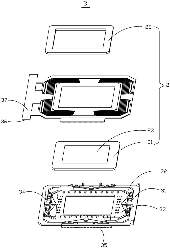
[0031]The driving module 3 includes a fixed part 31 , a movable part 32 , a bearing part 33 , a first driving assembly 34 and a second driving assembly 35 . Wherein, the fixed part 31, the movable part 32 and the bearing part 33 are all rectangular frames, and the optical sensor 2 is rectangular. The fixed part 31 is provided with a first movable chamber 311, the movable part 32 is provided with a second movable...


PUM


Abstract

The invention relates to an optical driving assembly. The optical driving assembly comprises an optical element with an optical axis, an optical sensor arranged along the optical axis with the optical element, and a driving module for driving the optical sensor to translate in a direction perpendicular to the optical axis. The driving module comprises: a fixed part having a first movable cavity; a movable part arranged in the first movable cavity, wherein the movable part is movably connected with the fixed part in the first direction, and a second movable cavity is formed in the movable part; a bearing part arranged in the second movable cavity, wherein is movably connected with the movable part in the second direction and bears the optical sensor; a first driving assembly comprising a first shape memory alloy wire which is connected with the fixed part and the movable part respectively; and a second driving assembly comprising a second shape memory alloy wire which is respectively connected with the movable part and the bearing part. Through the above mode, the optical sensor performs linear motion on the vertical optical axis in two directions, optical anti-vibration is realized, and the motion in the two directions is independently controlled and does not influence each other.

Description

【Technical field】 [0001] The invention relates to the technical field of optical imaging equipment, in particular to an optical drive assembly. 【Background technique】 [0002] The current Optical Image Stabilization (OIS) solution for smart electronic devices is mainly realized by using a Voice Coil Motor (Voice Coil Motor, VCM) to drive the lens to perform angle correction. However, this type of solution has disadvantages such as high power consumption, limited anti-shake effect, large product size and high unit price. [0003] Therefore, it is necessary to provide a new optical drive assembly to solve the existing defects. 【Content of invention】 [0004] The object of the present invention is to provide an optical drive assembly, through the arrangement of the fixed part, the movable part, the bearing part and the optical sensor and the matching of the first SAM line and the second SAM line, the image optical sensor in the optical drive assembly can be moved to achieve ...

Claims


Application Information

Patent Timeline
Patent Type & Authority Applications(China)
IPC IPC(8): G02B27/64
CPCG02B27/646H04N23/55H04N23/687G03B2205/0076G03B2205/0038H04N23/54G03B5/00G03B2205/0007
Inventor 张伯维李承峻陈世轩苏旅昂刘璧瑄廖翌君黃圆媚
Owner CHANGZHOU RAYTECH OPTRONICS CO LTD
Learn More