
Optical module and backlight module

An optical module and optical lens technology, which is applied in the field of optical modules with optical characteristics and backlight modules, can solve the problems such as the inability to control the adjustment effect of the ink layer, the inability to track and control the specifications of the ink layer, etc., and achieve the effect of ensuring the display effect.

Pending Publication Date: 2021-11-12
LEXTAR ELECTRONICS(CHUZHOU) CORP
View PDF0 Cites 0 Cited by
  • Summary
  • Abstract
  • Description
  • Claims
  • Application Information

AI Technical Summary

Problems solved by technology

In order to improve the light uniformity of the backlight, an ink layer will be placed on the circuit board corresponding to the light-emitting components (such as LED lamp beads) to adjust the light. However, due to the special printing area, the specification of the ink layer cannot be tracked and controlled. The adjustment effect of the ink layer can not be controlled

Method used


Image

  • Optical module and backlight module
  • Optical module and backlight module
  • Optical module and backlight module

Examples


Embodiment Construction

[0020] In order to have a further understanding of the purpose, structure, features, and functions of the present invention, the following detailed descriptions are provided in conjunction with the embodiments.

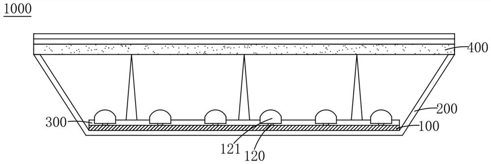
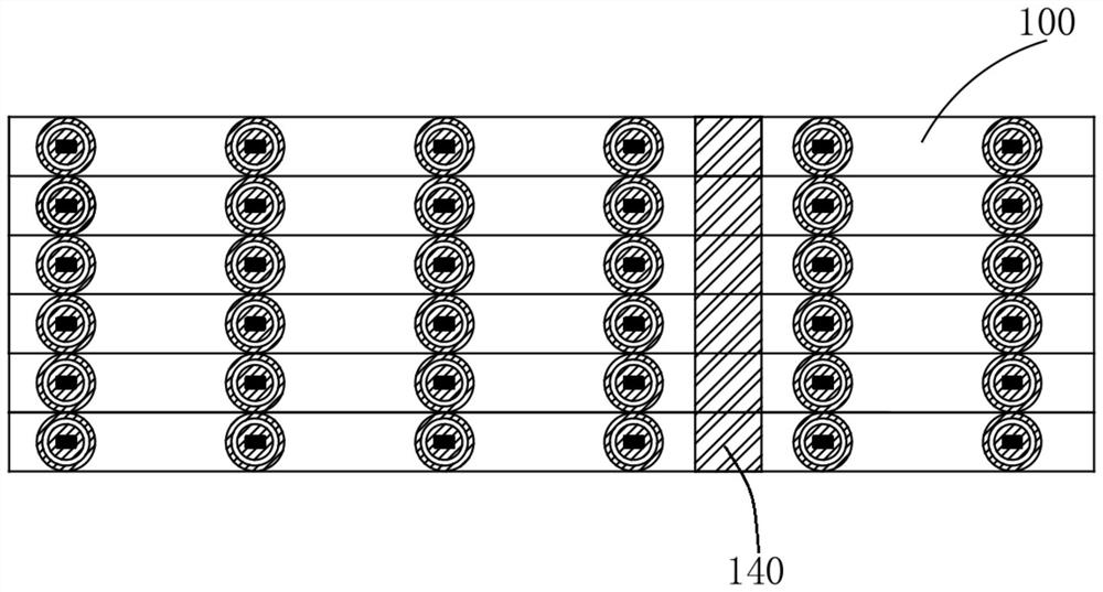
[0021] Please refer to Figure 1 to Figure 3 , figure 1 It is a cross-sectional view of the backlight module of the present invention; figure 2 for figure 1 The top view of the optical module in the middle; image 3 It is a partial schematic diagram of the optical module of the present invention. Such as figure 1 As shown, the backlight module 1000 of the present invention includes an optical module 100 , a bottom plate 200 , a reflection sheet 300 and a quantum dot film 400 . The optical module 100 is disposed between the bottom plate 200 and the reflective sheet 300 , and the quantum dot film 400 is disposed on the reflective sheet 300 and the optical module 100 .

[0022] Such as figure 2 and image 3 As shown, the optical module 100 of the present invent...


PUM


Abstract

The invention discloses an optical module and a backlight module. The optical module comprises a circuit board, a first light-emitting element, a first optical adjustment layer and a detection block. The first light-emitting element is arranged on the circuit board; the first optical adjustment layer is arranged on the circuit board corresponding to the first light-emitting element; the detection block is arranged on the circuit board, and the detection block and the first optical adjustment layer are formed through the same process; the detection block is used for detecting to confirm the optical characteristics of the first optical adjustment layer. According to the invention, the detection block and the optical adjustment layer corresponding to the optical element are formed on the circuit board by adopting the same process, and the optical characteristics of the optical adjustment layer are known by detecting the detection block, so that the optical adjustment layer can be tracked and controlled; the optical adjustment effect of the optical adjustment layer on the corresponding light-emitting element is ensured, and then the display effect of the backlight module and the display device is ensured.

Description

technical field [0001] The invention relates to an optical module and a backlight module, in particular to an optical module and a backlight module capable of detecting the optical characteristics of an optical adjustment layer. Background technique [0002] With the continuous development of liquid crystal display technology, the requirements for the backlight module supplying the light source of the liquid crystal display panel are also getting higher and higher. In order to improve the light uniformity of the backlight, an ink layer will be placed on the circuit board corresponding to the light-emitting components (such as LED lamp beads) to adjust the light. However, due to the special printing area, the specification of the ink layer cannot be tracked and controlled. The effect of adjusting the ink layer cannot be controlled. Contents of the invention [0003] The purpose of the present invention is to provide an optical module and a backlight module to solve the abo...

Claims


Application Information

Patent Timeline
Patent Type & Authority Applications(China)
IPC IPC(8): G02F1/13357
CPCG02F1/133602G02F1/133603
Inventor 吴昇达
Owner LEXTAR ELECTRONICS(CHUZHOU) CORP
Learn More