Supercharge Your Innovation With Domain-Expert AI Agents!

Processing module for robot

A technology for processing modules and robots, which is applied in the field of robotics and can solve problems such as crowding available bandwidth, increasing system complexity, and routing difficulties.

Pending Publication Date: 2021-11-12
ABB (SCHWEIZ) AG
View PDF0 Cites 0 Cited by
  • Summary
  • Abstract
  • Description
  • Claims
  • Application Information

AI Technical Summary

Problems solved by technology

This can make routing difficult and add complexity to the system
Alternatively, when data is transmitted wirelessly from the sensors to the robot controller, each sensor requires a separate signal path, which can crowd out available bandwidth

Method used


Image

  • Processing module for robot
  • Processing module for robot
  • Processing module for robot

Examples


Embodiment Construction

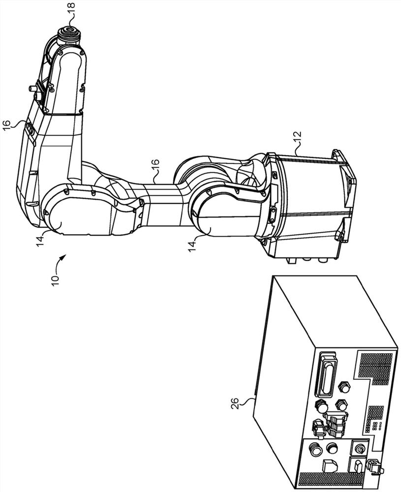
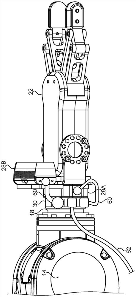
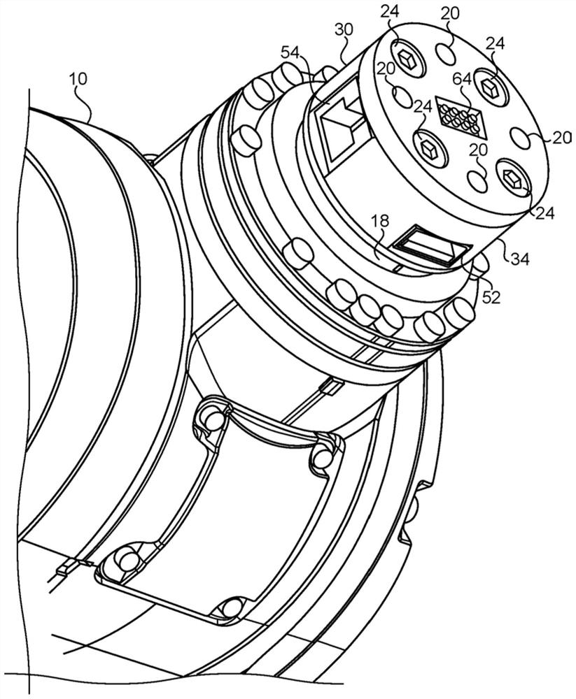
[0020] Referring now to the drawings, and in particular figure 1 , an example of a robot 10 is shown. As shown, the robot 10 has a base 12 which may be fixed in place or movable. The robot 10 is provided with one or more joints 14 that allow a member 16 of the robot 10 (eg, the arm 16 ) to be moved in different directions. although figure 1 A pivot joint 14 is illustrated in , but it is also possible that the joint 14 could be a linearly extendable joint, a rotational joint or other type of joint that allows movement between the two members 16 of the robot 10 . At the end opposite the base 12 , the robot 10 may be provided with a robot tool mounting surface 18 , or tool flange 18 . Preferably, the tool flange 18 (e.g., Figure 4 ) is an industry standard tool flange 18 that allows end effectors 22 of different manufacturers to be attached to the tool flange 18. For example, preferred industry standard tool flanges meet ISO 9409-1:2004(E). In particular, the tool flange 1...


PUM


Abstract

A processing module is provided for improving performance of a robot. The processing module is attached between the robot tool flange and the end effector. Additional interchangeable modules may also be provided between the tool flange and the end effector. The processing module includes a processor that processes sensor data received from one or more sensors. The processor generates lower bit rate processed sensor data from the incoming sensor data. The processed sensor data is transmitted from the processing module to another processor of a robot controller.

Description

Background technique [0001] The present invention relates generally to robots, and more particularly to a handling module positioned between a tool mounting surface of a robot and an end effector of said robot. [0002] Robots typically include a series of joints that allow the end effector to move from one place to another to perform various tasks. Typically, in order to enable the end effector to perform various tasks, one or more sensors are placed on or near the end effector to monitor the environment surrounding the end effector. The robot also includes a robot controller that collects data from and sends instructions to the joints, end effectors, and sensors. Typically, the robot controller can be located in or near the base of the robot, or in a separate computer a short distance from the robot, although it is also possible for the robot controller to be located in a remote location where communication between the robot and the controller over a wide area network. ...

Claims


Application Information

Patent Timeline
Patent Type & Authority Applications(China)
IPC IPC(8): B25J9/16B25J9/08B25J9/18B25J13/00B25J13/08B25J19/00B25J19/02
CPCB25J19/0054B25J15/04B25J13/08B25J19/02B25J19/0033B25J9/161G05B2219/34012B25J17/02B25J19/021B25J19/026B25J9/1694B25J13/06B25J15/0019B25J18/00
Inventor 马特·西姆金斯赛德·扎哈伊
Owner ABB (SCHWEIZ) AG
Features
  • R&D
  • Intellectual Property
  • Life Sciences
  • Materials
  • Tech Scout
  • Unparalleled Data Quality
  • Higher Quality Content
  • 60% Fewer Hallucinations
Learn More